Light source device and projecting display device provided with light source device

A technology for a light source device and a light-emitting part, which is applied to the cooling/heating device, electric light source, lighting device, etc. of the lighting device, can solve the problems of shortening the life of the light-emitting tube, excessive increase in the temperature of the light-emitting tube, and increasing the replacement frequency of the light-emitting tube.

Inactive Publication Date: 2015-03-11
NEC DISPLAY SOLUTIONS LTD
View PDF6 Cites 2 Cited by
  • Summary
  • Abstract
  • Description
  • Claims
  • Application Information

AI Technical Summary

Problems solved by technology

[0006] However, the arc tube generates heat along with the light emission of the light emitting part, and the temperature of the arc tube may rise excessively.
It is known that when the temperature of the arc tube rises, the brightness of the arc tube decreases or the life of the arc tube shortens.
[0007] When the brightness of the luminous tube is reduced, the brightness of the projection display device is reduced
Also, when the lifetime of the luminous tube is shortened, the replacement frequency of the luminous tube increases

Method used


Image

  • Light source device and projecting display device provided with light source device
  • Light source device and projecting display device provided with light source device
  • Light source device and projecting display device provided with light source device

Examples


Embodiment Construction

[0049] Next, embodiments of the present invention will be described with reference to the drawings.

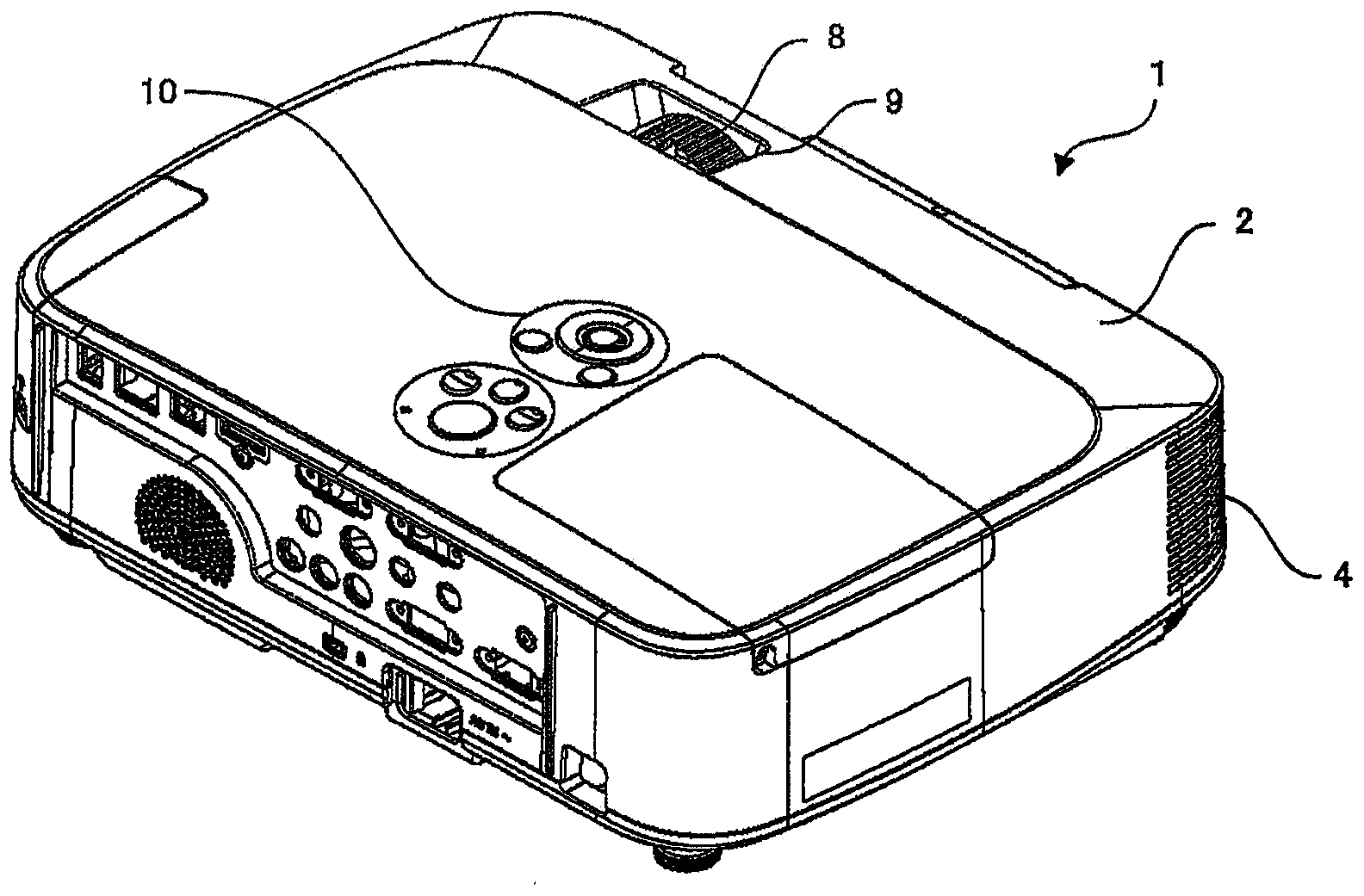
[0050] figure 1 It is a perspective view of a projection display device to which the light source device according to the present embodiment can be applied. like figure 1 As shown, the projection display device 1 includes a housing 2 . An air inlet (not shown) is formed on the left side of the housing 2 , and an air outlet 4 is formed on the front surface of the housing 2 . The cooling air flows into the inside of the housing 2 through the air intake port to cool the inside of the housing 2 , and then is discharged to the outside of the housing 2 through the exhaust port 4 .

[0051] figure 2 It is a perspective view of main components of the projection display device 1 accommodated inside the housing 2 . like figure 2 As shown, the projection display device 1 includes: a light source device 5 ; an optical engine 6 that uses light from the light source device 5 to form...


PUM


Abstract

Provided is a light source device that can more uniformly cool a light-emitting tube. The light source device is provided with a reflector (15), a light-emitting tube (14), a blower (12), a first duct (21), and a second duct (41). The reflector (15) has a through hole. The light-emitting tube (14) contains a light-emitting section (17) and a sealing section (18) extending from the light-emitting section (17). Also, the sealing section (18) is passed through the through hole. The blower (12) generates cooling wind. The first duct (21) leads the cooling wind to the light-emitting section (17). The second duct (41) leads the cooling wind to the sealing section (18).

Description

technical field [0001] The present invention relates to a light source device having a light emitting tube and a projection display device provided with the light source device. In particular, it relates to a light source device capable of cooling an arc tube. Background technique [0002] Projection display devices that project images are known. As a light source of a projection display device, an arc tube such as a high-pressure mercury lamp may be used. The luminous tube includes: a luminous portion that emits light through discharge; and two sealing portions that extend from the luminous portion in opposite directions to each other. [0003] In a projection display device, light from a light emitting unit is converted into a light beam traveling in a predetermined direction by a reflector. Specifically, the reflecting mirror has an open shape by removing the bottom surface of a hollow substantially hemisphere, and surrounds the light emitting part. Accordingly, the r...

Claims


Application Information

Patent Timeline
IPC IPC(8): F21V29/67
CPCG03B21/16G03B21/2026F21S2/00F21V29/67
Inventor 山下荣介
Owner NEC DISPLAY SOLUTIONS LTD
Why Eureka
Try Eureka