cuff blood pressure monitor

A sphygmomanometer and cuff technology, applied in vascular assessment, cardiac catheterization and other directions, can solve the problems of difficulty in unlocking, deviation of auxiliary unlocking tool operation, low efficiency of cuff removal, etc., and achieve the effect of improving efficiency and reliability.

Active Publication Date: 2016-08-17
BEIJING KANGKANG SHENGSHI INFORMATION TECH
View PDF5 Cites 0 Cited by
  • Summary
  • Abstract
  • Description
  • Claims
  • Application Information

AI Technical Summary

Problems solved by technology

[0007] For this reason, the object of the present invention is to solve the problem of low cuff removal efficiency in the prior art, and the auxiliary unlocking tool is prone to operation deviation during the unlocking process, thereby causing difficulty in unlocking. The present invention provides a cuff-type sphygmomanometer

Method used


Image

  • cuff blood pressure monitor
  • cuff blood pressure monitor
  • cuff blood pressure monitor

Examples


Embodiment Construction

[0030] In order to make the object, technical solution and advantages of the present invention clearer, the implementation manner of the present invention will be further described in detail below in conjunction with the accompanying drawings.

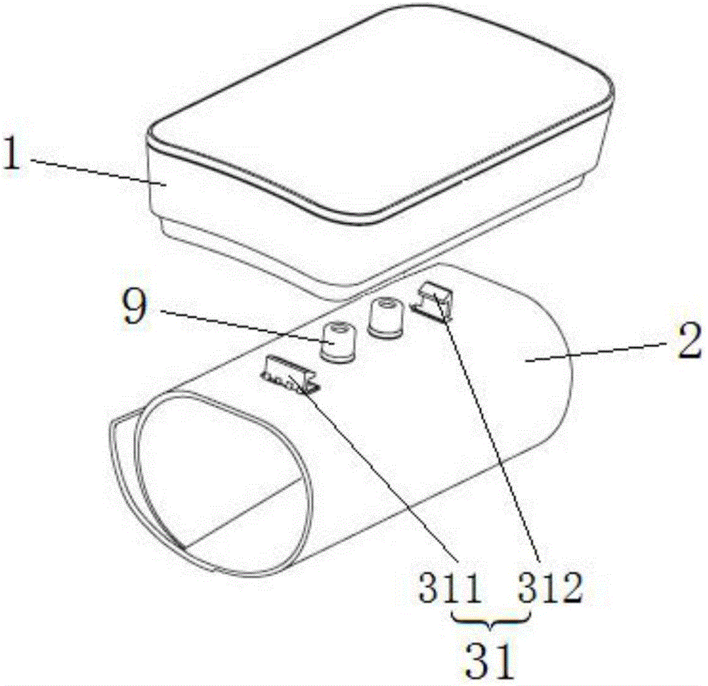
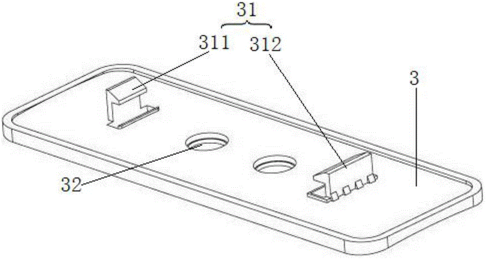
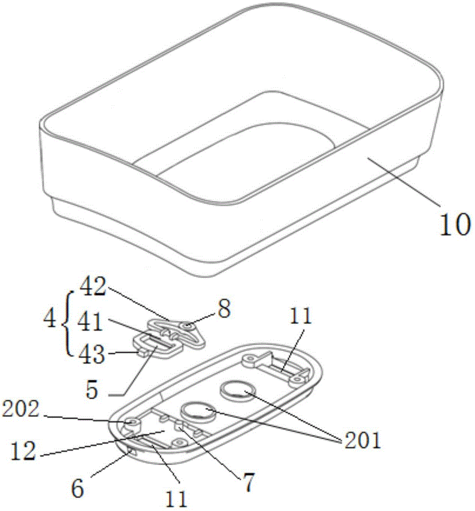
[0031] Such as figure 1 and figure 2 As shown, the present invention provides a cuff-type sphygmomanometer, which includes a sphygmomanometer lower housing 1 and a cuff 2. An adapter plate 3 is provided on the cuff 2, and two cards arranged at intervals are formed on the adapter plate 3. The hooks 31 are respectively the first hook 311 and the second hook 312. The lower housing 1 of the sphygmomanometer is provided with two hook channels 11 corresponding to the two hooks 31, as image 3 shown and Figure 4 As shown, the two hook channels are the first hook channel 111 and the second hook channel 112 respectively. image 3 The lower housing 1 of the sphygmomanometer shown in the figure is composed of a lower cover 10 and a chassis 2...


PUM


Abstract

The invention discloses a cuff type sphygmomanometer. The cuff type sphygmomanometer comprises a lower housing and a cuff; an adapter plate is arranged on the cuff; two clamping hooks which are arranged at intervals are formed on the adapter plate; two clamping hook channels corresponding to the two clamping hooks are arranged on the lower housing; an elastic locking mechanism is arranged on the inner side bottom surface of the lower housing; a clamping slot is formed in the elastic locking mechanism and communicates with one of the two clamping hook channels; when in mounting, one of the two clamping hooks sequentially passes through the clamping hook channels and the clamping slot and then is clamped to the elastic locking mechanism; an unlocking hole for unlocking the elastic locking mechanism is arranged on the lower housing; when in mounting, the elastic locking mechanism is telescoped to enable the clamping hooks to be completely clamped to the elastic locking mechanism; when in dismounting, an auxiliary unlocking tool extends into the unlocking hole to directly apply the acting force on the elastic locking mechanism, and thus the two clamping hooks can be separated from the clamping hook channels; therefore, the dismounting efficiency and the cuff replacing efficiency can be improved.

Description

technical field [0001] The invention relates to the technical field of blood pressure measurement, in particular to a cuff type blood pressure monitor. Background technique [0002] Electronic sphygmomanometers usually include a host and a cuff. Some of the sphygmomanometers currently on the market adopt an integrated design. The combination of the cuff and the host body is realized through certain mechanical structures or special small parts. A common coupling mechanism is that the buckle protrudes from the cuff and is inserted into the opening provided at the lower part of the housing. Although this structure is simple, it is difficult to operate, which brings inconvenience to maintenance or replacement of parts, and there is a risk of deformation and damage to the mechanism due to excessive external force. [0003] Chinese patent document CN 102813510 discloses an electronic sphygmomanometer, including: a body and a cuff, and the cuff includes a liner, wherein at least o...

Claims


Application Information

Patent Timeline
Patent Type & Authority Patents(China)
IPC IPC(8): A61B5/022
CPCA61B5/02141A61B5/02233
Inventor 曾明发杨胜周李晨亮郑炜
Owner BEIJING KANGKANG SHENGSHI INFORMATION TECH
Why Eureka
Try Eureka