

a device
A packaging box and box body technology, applied in the electronic field, can solve the problems of single function application and low applicability, and achieve the effect of improving sound transmission quality and sound transmission efficiency
- Summary
- Abstract
- Description
- Claims
- Application Information
AI Technical Summary
Problems solved by technology
Method used
Image

Examples
Embodiment 1
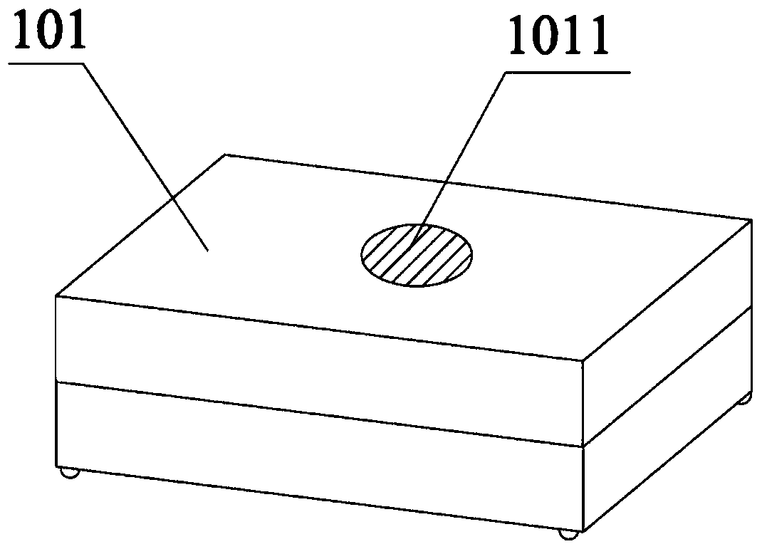
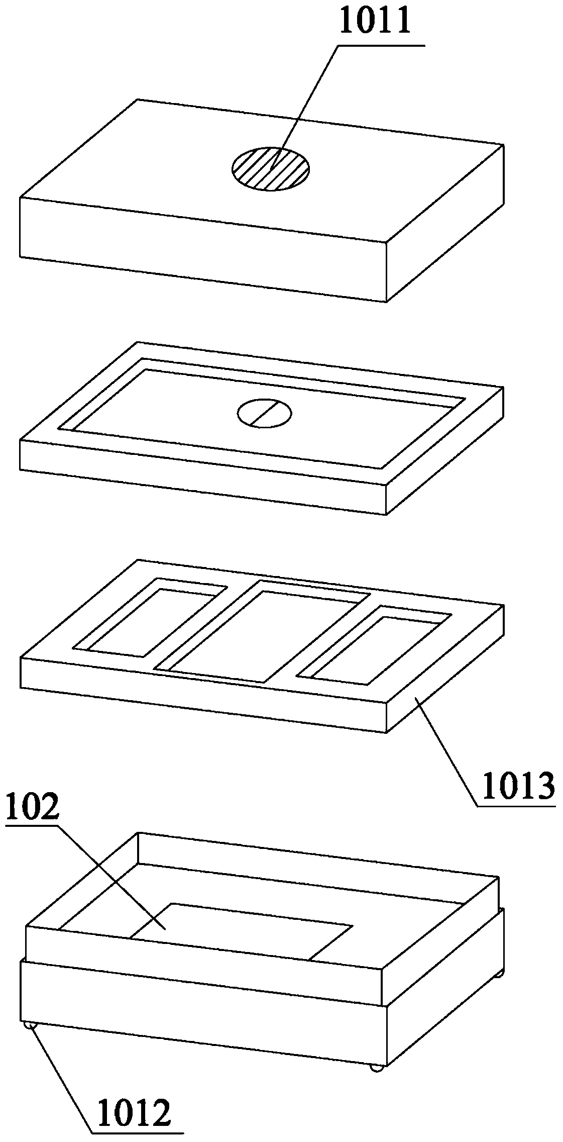
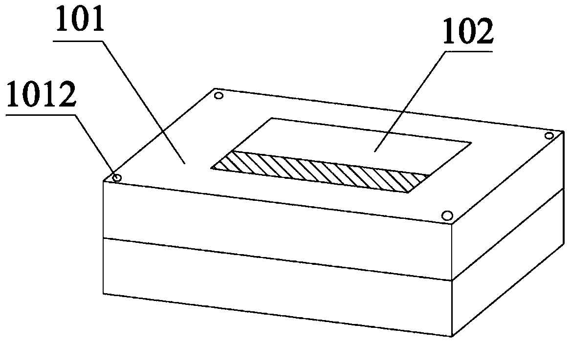
[0048] Please refer to figure 1 , figure 2 , image 3 , Embodiment 1 of the present application provides a packing box, including:
[0049] A box body 101, the box body is a cavity structure, and the cavity structure is used to place electronic equipment;
[0050] The hole 102 is used to transmit the sound emitted by the electronic equipment placed in the cavity to the space outside the box.
[0051] The box body can be a sealed cavity structure when in use, and the electronic device can be directly placed in the box body when not in use or unopened, and can be opened by opening the box cover or from the box when in use. Take out the electronic device from the packaging box by means of the opening on the body or the like.
[0052] The number of the holes can be one or more, and the setting position can be the position corresponding to the output port of the power amplifier of the electronic device, and of course can also be set at other positions, as long as the sound fro...
Embodiment 2
[0070] Please refer to Figure 4 , Embodiment 2 of the present application provides an electronic device, including:
[0071] A main body 201, the main body includes at least an audio output device 2011, and the audio output device includes a first connection end 2012;
[0072] The rear cover 202, the rear cover includes:
[0073] The second connecting end 2021 is used for connecting with the first connecting end when the rear cover and the main body are combined together;
[0074] The sound transmission vibrating plate 2022 is used for receiving the audio voltage output from the audio output device through the first connection end, and generating mechanical vibration.
[0075] In actual operation, the structure of the first connection end may be a component corresponding to the structure of the second connection end, that is to say, when the main body and the rear cover are combined, the first connection end may be the same as that of the second connection end. The bonding...
Embodiment 3
[0087] Please refer to Figure 5 Embodiment 3 of the present application provides an electronic device, including a packaging box and a first device, and the packaging box includes:
[0088] A box body, the box body is a cavity structure, and the cavity structure is used to place electronic equipment;
[0089] The hole is used for transmitting the sound emitted by the electronic equipment placed in the cavity to the space outside the box.
[0090] The first device includes:
[0091] a main body, the main body includes at least an audio output device, and the audio output device includes a first connection end;
[0092] The rear cover, the rear cover includes:
[0093] the second connecting end is used to connect with the first connecting end when the rear cover and the main body are combined together;
[0094] The sound-transmitting vibrating piece is used to receive the audio voltage output from the audio output device through the first connection end, and generate mechan...
PUM
 Abstract
Description
Claims
Application Information