Vortex type flame combustion device

A flame combustion and vortex technology, applied in the direction of burner, combustion method, combustion type, etc., can solve the problems that the combustion device cannot reduce the flame height and the obvious vortex shape

Active Publication Date: 2015-09-16
PRO IRODA INDS
View PDF12 Cites 1 Cited by
  • Summary
  • Abstract
  • Description
  • Claims
  • Application Information

AI Technical Summary

Problems solved by technology

[0007] The technical problem to be solved by the present invention is that the traditional combustion device for generating a vortex flame cannot shrink and maintain a stable flame heig

Method used


Image

  • Vortex type flame combustion device
  • Vortex type flame combustion device
  • Vortex type flame combustion device

Examples


Embodiment Construction

[0035] Regarding the technology, means and effects adopted by the present invention, two preferred embodiments are given and described in detail below with accompanying drawings, which are for illustration purposes only, and are not limited by this structure in patent applications.

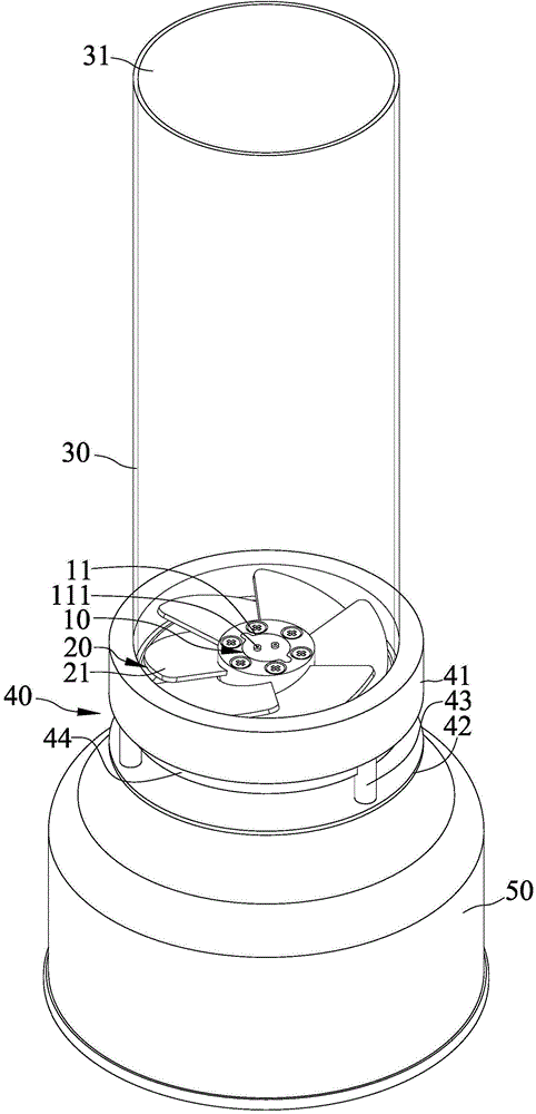
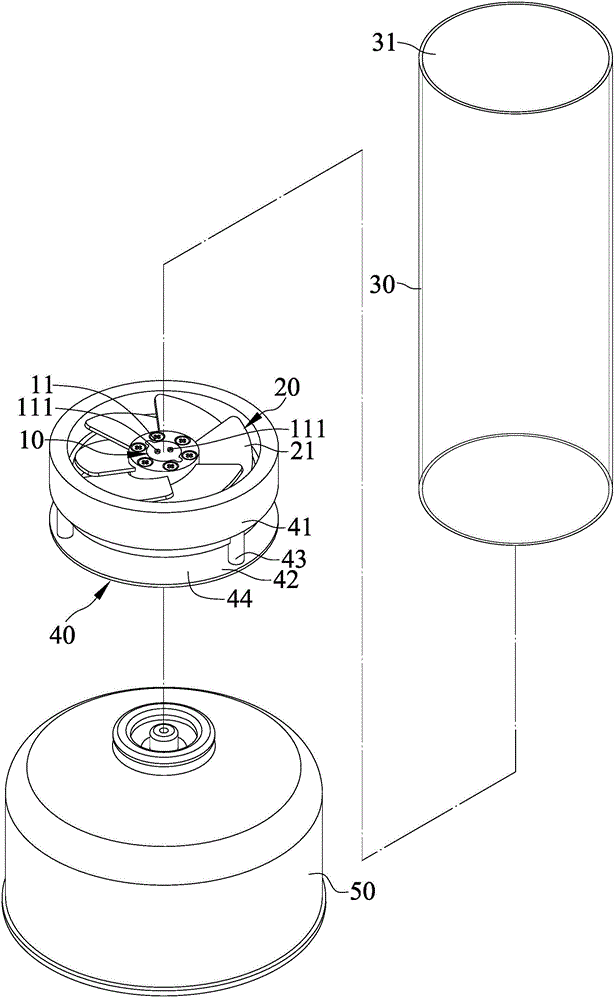
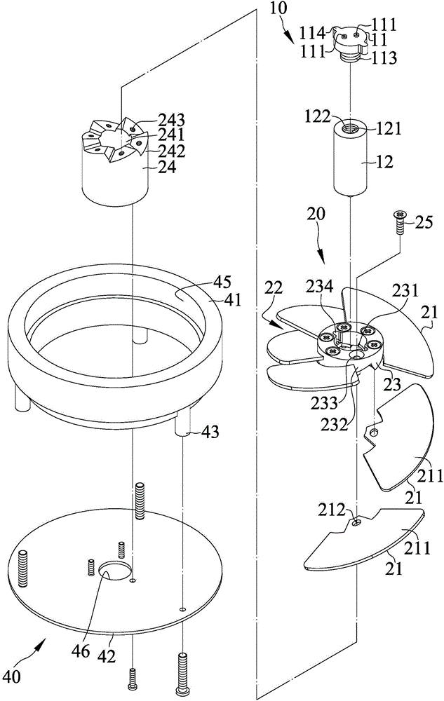
[0036] Please refer to Figure 1 to Figure 6 , is a three-dimensional appearance view, an exploded view and a sectional view of the first embodiment of the vortex flame combustion device of the present invention. The vortex flame combustion device includes a nozzle 10 , a guide group 20 , a cover body 30 and a supporting base 40 . The deflector group 20 is arranged on the outer periphery of the nozzle 10, the cover body 30 is connected to and leans against the support base 40, and the cover body 30 is provided on the deflector group 20 and the nozzle 10, the support The seat 40 is connected to the flow guiding group 20 and is provided to abut against a fuel tank 50 .

[0037] The nozzle 10 inclu...


PUM

PropertyMeasurementUnit
Angleaaaaaaaaaa

Abstract

The invention discloses a vortex type flame combustion device. The vortex type flame combustion device comprises a nozzle, wherein the nozzle has a nozzle head, a nozzle body, a first air chamber and a second air chamber; the nozzle head and the nozzle body are detachably connected; the nozzle head comprises two air outlet ways; the first air chamber is communicated with the two air outlet ways; the second air chamber is communicated with the first air chamber; one end, far from the first air chamber, of the second air chamber can be connected with a fuel tank; a guide set is arranged at the outer periphery of the nozzle, and comprises multiple blades; all the blades are spirally and uniformly distributed in the peripheral direction of the nozzle; air guide channels are formed between every two adjacent blades for passing through air; a cover covers the guide set, and can transmit light; and the cover is communicated with the two air outlet ways of the nozzle head and the air guide channels of the guide set.

Description

technical field [0001] The invention mainly discloses a flame combustion device, especially a combustion device capable of effectively generating swirl flames. Background technique [0002] Refer to US Patent No. 7097448 "VORTEX TYPE GAS LAMP" patent case, which discloses a vortex type gas lamp (gas lamp) for combustible gas to generate an upward vortex flame, and the vortex flame is located in a surrounding And limited within the boundary of the vortex air, there will be an interface between the gas-free vortex air and the central area surrounded by the gas during operation, and the gas will burn inside it. The gas lamp has a central axis (axis) and includes: a base (base) with a surface extending laterally along the central axis; a shield (shield) including a first, a second axially extending block (section) , each block has an upper end and a lower end, the lower end of each block is fluid-tightly combined with the base, each block is almost identical and transparent, ea...

Claims


Application Information

Patent Timeline
IPC IPC(8): F23D14/24F23D14/58F23D14/70
CPCF23D14/24F23D14/58F23D14/70
Inventor 陈维隆
Owner PRO IRODA INDS
Why Eureka
Try Eureka