Metal elastic contact

An elastic contact and elastic technology, applied in the direction of clamping/spring connection, coupling device, structural parts, etc., can solve the problems of corrosion, conductive group conductivity weakening, melting, etc., to reduce manufacturing costs, avoid serious temperature rise, The effect of improving the service life

Active Publication Date: 2018-10-26
GUANGDONG MENLO ELECTRIC POWER
View PDF7 Cites 0 Cited by
  • Summary
  • Abstract
  • Description
  • Claims
  • Application Information

AI Technical Summary

Problems solved by technology

The conductive group in this structure is the conductive elastic contact, which is composed of a conductive cylinder seat, a conductive cap and an extension spring. Its structure is complex and the cost is high
In addition, due to the sliding fit between the conductive cap and the inner cavity of the conductive cylinder seat, when dirt accumulates in the gap between the two, it is easy to get stuck; or, when the conductive group is applied to other high-power electric facilities, the conductive cap and the conductive cylinder seat The fit gap is prone to sparking and melting, which makes the two connected together, loses elasticity, reduces the compression degree when it contacts with other conductive contacts, and weakens the conductive effect
Furthermore, because the conductive group is in a closed structure, its heat dissipation effect is poor, so that the temperature rise of the conductive group is serious
In addition, the sliding fit between the conductive cap and the conductive cylinder seat causes irregular shaking of the stretching spring during telescopic movement. Therefore, after the conductive group is used for a long time, the mating surface between the conductive cap and the conductive cylinder seat has irregular wear , so that the matching gap between the conductive cap and the conductive cylinder seat increases, so that the conductive effect is weakened; in addition, although the conduction between the conductive cap and the conductive cylinder seat can be conducted through the stretch spring, the conductivity of the metal material for the stretch spring is not good. Good, the corrosion of the conductive coating on the surface of the stretch spring makes the conductivity of the conductive group weaken quickly, especially in the field of high-power (strong current) electric power, and occasions that require long-term opening and closing work, which can reflect the above The conductive group has a shorter service life

Method used


Image

  • Metal elastic contact
  • Metal elastic contact
  • Metal elastic contact

Examples


Embodiment 1

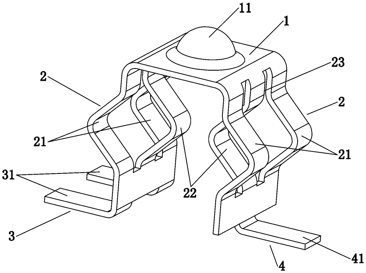
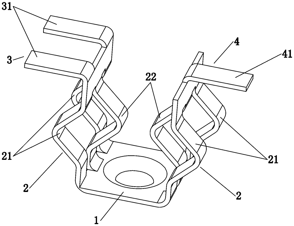
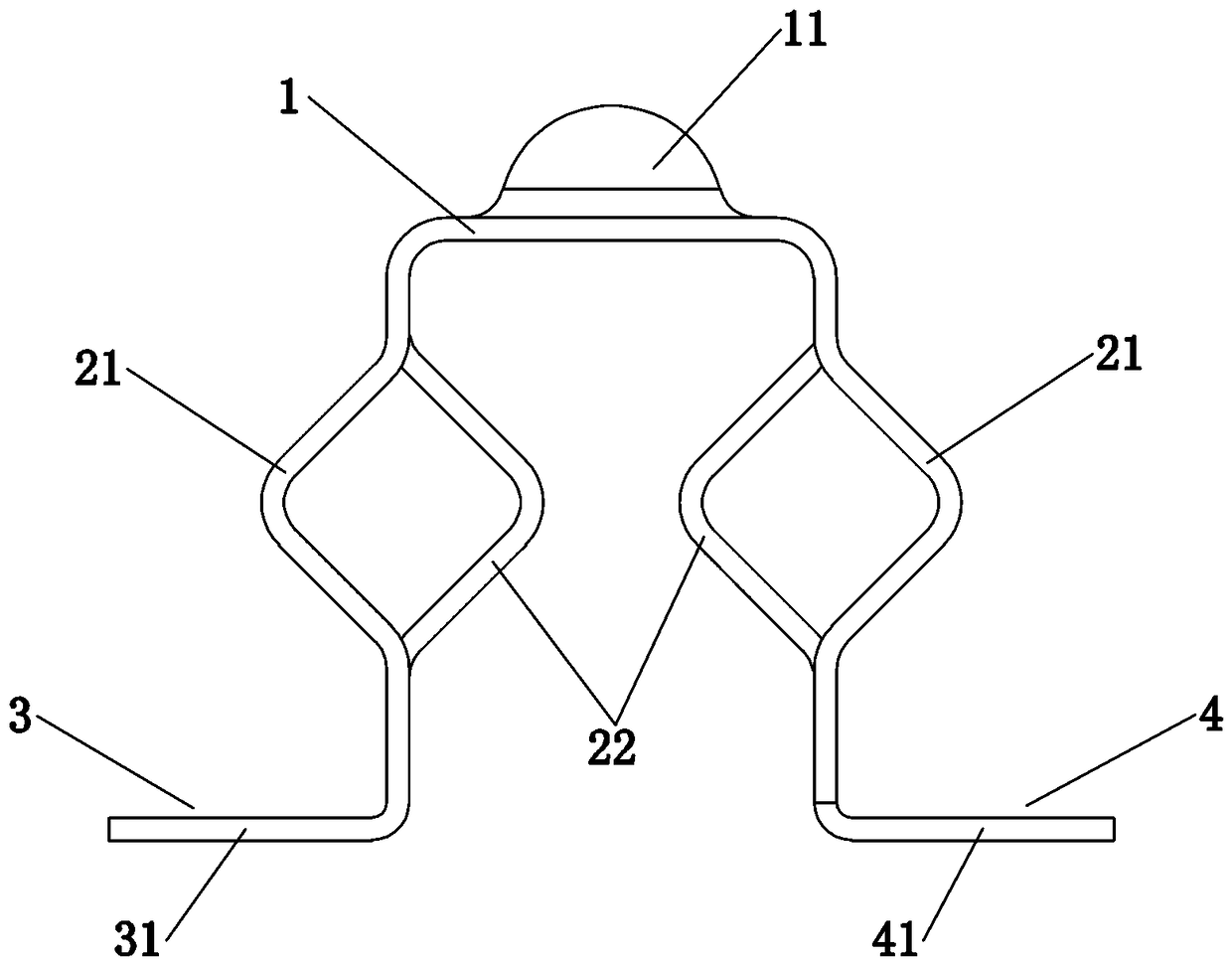
[0030] Embodiment one, see Figure 1 to Figure 3 As shown, a metal elastic contact includes an elastic contact bent from a metal sheet, and the elastic contact includes an elastic contact surface 1, an elastic support surface 2 and a fixed support arranged in sequence from top to bottom At least two edges of the elastic contact surface 1 are respectively provided with the elastic support surface 2, and the lower end of each elastic support surface 2 is provided with the fixed support surface.

[0031] The surface of the elastic contact surface 1 is provided with convex points 11 (or, the surface of the elastic contact surface 1 is provided with concave points 12, see Figure 4 and Figure 8 shown). The elastic contact surface 1 is square, and the elastic support surfaces 2 are respectively provided on the left and right edges.

[0032] The elastic support surface 2 is vertically provided with two separation grooves 23, and the two separation grooves 23 separate the elastic ...

Embodiment 2

[0037] Embodiment two, the difference with embodiment one is: see Figure 7 As shown, the left fixed support foot 31 and the right fixed support foot 41 are both pin-type fixed support feet arranged vertically.


PUM


Abstract

The invention relates to a metal elastic contact, which comprises an elastic contact bent from a piece of metal sheet, and the elastic contact includes an elastic contact surface, an elastic support surface and a fixed support surface sequentially arranged from top to bottom , at least two edges of the elastic contact surface are respectively provided with the elastic support surface, and the lower end of each elastic support surface is provided with the fixed support surface. The elastic support surface of this metal elastic contact is supported by at least two elastic support surfaces, so that the elastic support surface is in a relatively balanced state. , There is no poor contact between parts, so it has the advantages of low cost, easy processing, reliable operation, and long life.

Description

technical field [0001] The invention relates to a conductive elastic contact, in particular to a hardware elastic contact. Background technique [0002] Existing conductive elastic contacts for electronic products or power facilities can be found in Chinese Patent Announcement No. 202585849U, which disclosed a lithium battery conductive group structure for a handheld device on December 5, 2012, including: a conductive cylinder seat, and the inner end surface of the bottom plate Punch a positioning hole to fix the power supply position of the existing hand-held device circuit (that is, the bottom of the torch holder is used for fixed connection with the circuit), and roll a lip ring on the other end opening; a conductive cap, the open end slides in the conductive cylinder holder , the other end of the pressure contact is connected with a shoulder; one extension spring, one end is placed in the pressure contact of the conductive cap, and the other end is placed in the position...

Claims


Application Information

Patent Timeline
Patent Type & Authority Patents(China)
IPC IPC(8): H01R12/57H01R12/71H01R4/48H01M2/20H01M50/289
CPCH01R4/4881H01R12/57H01R12/718H01M50/50Y02E60/10
Inventor 韩贞友孔星陈思达
Owner GUANGDONG MENLO ELECTRIC POWER
Why Eureka
Try Eureka