Micro limit general switch based on double elastic components

A technology of elastic parts and elastic components, applied in the field of micro-motion limit switches, can solve the problems of poor contact, non-compliance with industry standards, low switch safety factor, etc., and achieve the effect of avoiding aging

Active Publication Date: 2017-09-05
ZHANGZHOU JUANMEI ELECTRIC TECH CO LTD
View PDF5 Cites 9 Cited by
  • Summary
  • Abstract
  • Description
  • Claims
  • Application Information

AI Technical Summary

Problems solved by technology

[0004] (1) It is impossible to realize the forced separation between the dynamic and static contacts, which does not meet the requirements of industry standards, and the safety factor of the switch is low, so it cannot be used in occasions with safety requirements, such as elevators;
[0005] (2) The switch is switched by the deformation of the single metal shrapnel or the elastic force generated by the tension of the single spring. At the critical position of the switch jump, there will be a balance in the process of switching the contact piece from normally closed to normally open, resulting in the switch being normally open. Or the normally closed connectors are not energized or the contact between the dynamic and static contacts is poor, causing the switch signal to flicker, making the equipment unusable, such as household ice machines, etc.;
[0006] (3) The structure size of the micro switch itself is small, resulting in a small cross-sectional area of ​​the conductive metal sheet, which cannot withstand a large current, and it is easy to burn out in applications that require a large current, such as garden electric tools equipped with lithium batteries

Method used


Image

  • Micro limit general switch based on double elastic components
  • Micro limit general switch based on double elastic components
  • Micro limit general switch based on double elastic components

Examples


Embodiment Construction

[0042] The technical solution of the present invention will be further described below in conjunction with the accompanying drawings.

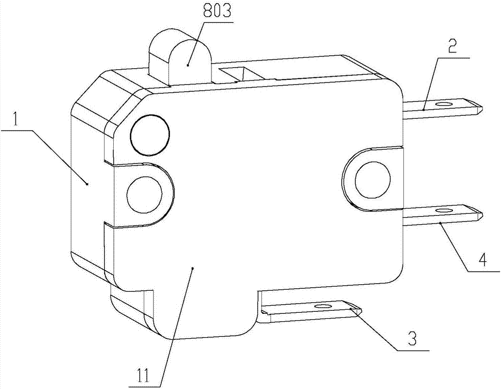
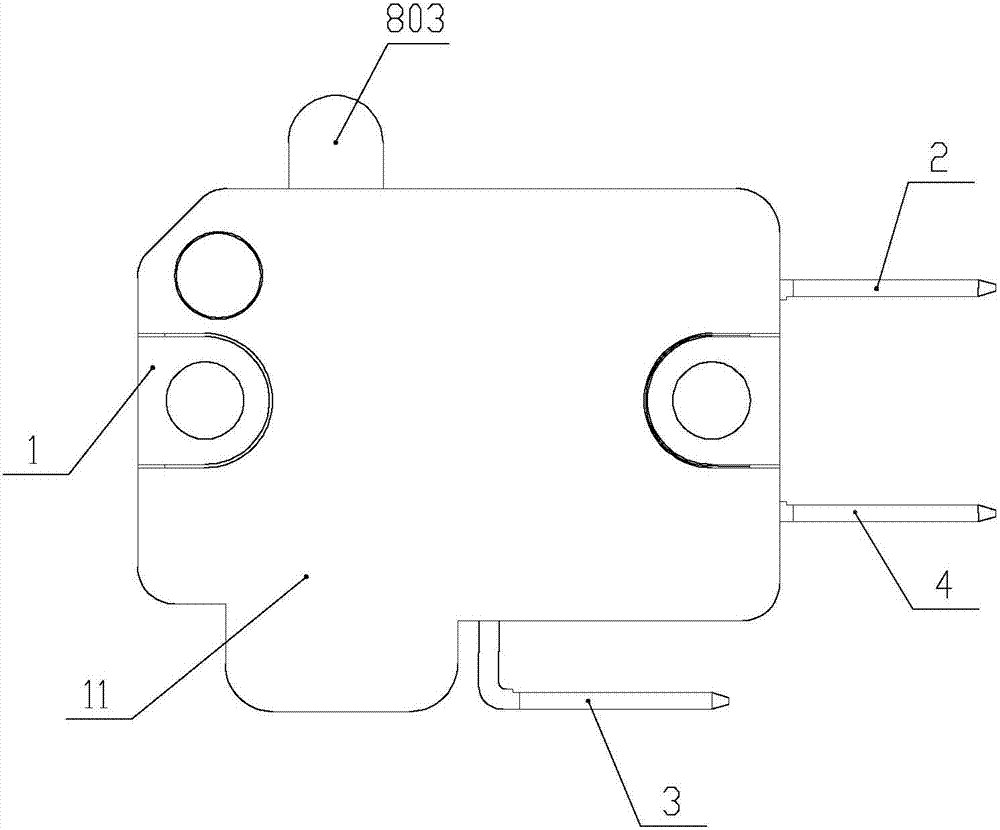
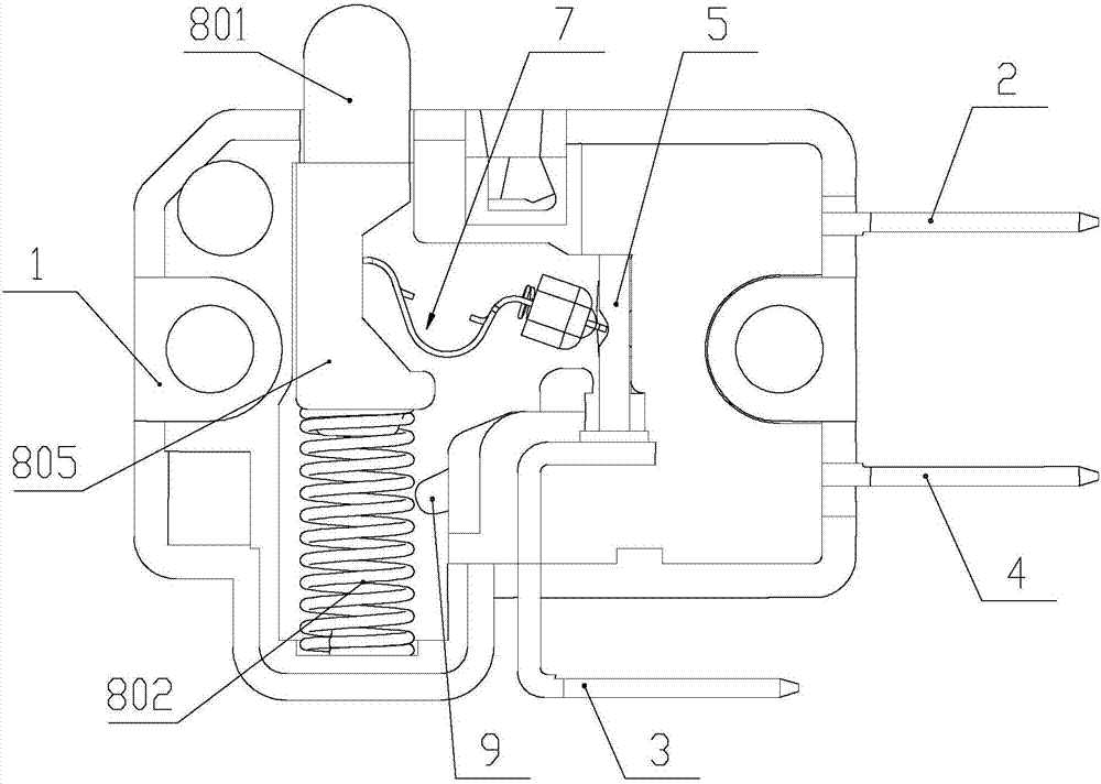
[0043] Such as figure 1 , figure 2 and image 3 As shown, the present invention is a kind of micro-movement limit universal switch based on double elastic parts, which includes a housing 1 and a face cover 11 adapted to the housing 1. The housing is provided with a normally open connector 2, a normally closed Connector 3 , common connector 4 , movable contact piece 5 , guide component 6 , elastic component 7 and trigger component 8 . One end of the normally open connector 2 and the common connector 4 protrudes from the same side of the housing as a plug terminal, and the other end of the normally open connector 2 and the common connector 4 is located in the housing 1, and the normally open connector 2 has a normally open contact for conducting or disconnecting with the movable contact piece 5. One end of the normally closed connector 3 is...


PUM


Abstract

The invention discloses a micro limit general switch based on double elastic components. The switch comprises a casing, the casing is internally provided with a normally-open connector, a normally-closed connector and a common connector, one end of each connector extends out of the casing, the casing is internally provided with a moving contact and a guiding assembly which limits the movement track of the moving contact, the moving contact is in linked connection with an elastic assembly and a triggering assembly successively, and the elastic assembly and the triggering assembly drive the moving contact to move; the elastic assembly comprises a main spring, an auxiliary spring which generates an auxiliary downward pressure and a movable block which is penetrated by the main spring and abuts against the guiding assembly in a swinging manner; and the movable block includes an arched contact surface which makes contact with an inclined plane of the guiding assembly. According to the invention, the elastic assembly services as a driving mechanism of the switch, generates an elastic force, and realizes switching of the switch; and in the switching process, the vertical pressure generated between the arched contact surface and the inclined plane of the guiding assembly acts on the moving contact, and a flickering or power-off phenomenon due to equilibrium and micro movement generated when the moving contact is jumped from a normally-closed state to a normally-open state or from the normally-open state to the normally-closed state is avoided.

Description

technical field [0001] The invention relates to a switch, in particular to a micro-movement limit universal switch based on double elastic parts. Background technique [0002] The micro switch is a contact mechanism with a small contact interval and a quick-action mechanism, which performs switching actions with a specified stroke and a specified force. It is covered with a casing and has a trigger rod on the outside. Small, hence the name micro switch. The external mechanical force acts on the action reed through the transmission element (press pin, button, lever, roller, etc.). Tap to quickly connect or disconnect. When the force on the transmission element is removed, the action reed produces a reverse action force, and when the reverse stroke of the transmission element reaches the action critical point of the reed, the reverse action is completed instantaneously. The contact spacing of the micro switch is small, the action stroke is short, the pressing force is small...

Claims


Application Information

Patent Timeline
Patent Type & Authority Applications(China)
IPC IPC(8): H01H13/52H01H13/14H01H13/26H01H1/50H01H1/58
CPCH01H1/50H01H1/58H01H13/14H01H13/26H01H13/52
Inventor 戴四川
Owner ZHANGZHOU JUANMEI ELECTRIC TECH CO LTD
Why Eureka
Try Eureka