Power supply plugging device capable of being locked safely

A power supply plugging and safety technology, which is applied to the parts of the connecting device, coupling devices, circuits, etc., can solve the problems of exposed power supply holes, unstable power supply connections, damaged power supply holes, etc., to increase the stability of power supply, device The operation is safe and reliable, and the effect of avoiding sudden power failure

Inactive Publication Date: 2017-11-24
YIWU MOYA OPTOELECTRONICS TECH CO LTD
View PDF4 Cites 15 Cited by
  • Summary
  • Abstract
  • Description
  • Claims
  • Application Information

AI Technical Summary

Problems solved by technology

[0002] Nowadays, the power-on of electrical equipment is basically to directly insert the plug connected to it into the power supply hole of the socket to cooperate, and the socket and the power supply connection will always be in the power-on state, although this plug-in method is simple to operate and relatively easy to use. It is convenient, but after the plug is inserted into the power supply hole, there are no other locking parts to lock the plug. Sudden power failure of electrical equipment will directly cause damage to electrical equipment in severe cases. Therefore, the existing plugging method has the risk of unstable power supply connection. In addition, when the electrical equipment is not in use, the plug is often inserted through the power supply hole Pull out the power supply hole, which will cause the power supply hole to be exposed. If a child inserts the metal rod into the power supply hole, it will not only damage the power supply hole but also cause an electric shock accident for the child, which poses a great safety hazard

Method used


Image

  • Power supply plugging device capable of being locked safely
  • Power supply plugging device capable of being locked safely
  • Power supply plugging device capable of being locked safely

Examples


Embodiment Construction

[0018] The preferred embodiments of the present invention will be described in detail below in conjunction with the accompanying drawings, so that the advantages and features of the present invention can be more easily understood by those skilled in the art, and the protection scope of the present invention will be defined more clearly.

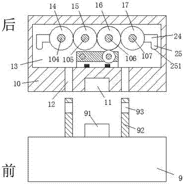
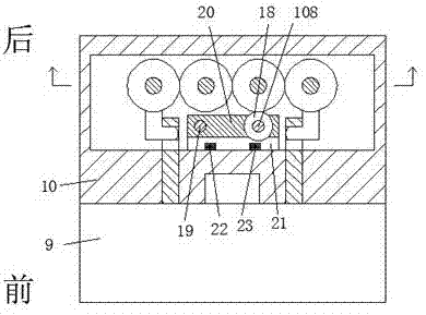
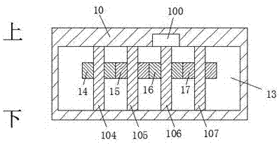
[0019] Refer to Figure 1-5 The shown safety lockable power supply plug-in device includes a socket body 10 arranged on a wall and a plug body 9 mated and connected to the socket body 10, and a middle position of the back end of the plug body 9 is provided Plug 91, the back end surface of the plug body 9 is provided with two insertion posts 92 symmetrically on the left and right sides of the plug 91, each of the two insertion posts 92 is provided with a locking groove 93 and two The locking grooves 93 are arranged opposite to each other, the socket body 10 is provided with a power supply hole 11 in the middle position of the front end surface fo...


PUM


Abstract

The invention discloses a safe lockable power supply plug-in device, which comprises a socket body arranged on the wall and a plug body connected with the socket body by plugging and mating. The rear end surface of the plug body is symmetrically provided with two posts on the left and right sides of the plug, each of the two posts is provided with a locking groove and the two locking grooves are arranged oppositely, and the socket A power supply hole is provided in the middle of the front face of the body for the insertion and connection of the plug. The socket body is provided with an accommodation cavity. The overall structure of the present invention is simple, and the power supply stability is good, which reduces electric shock accidents in existing life. The occurrence of the occurrence effectively guarantees the safety of people's life and property, and the operation of the whole device can be realized by a single motor, the structure setting is very reasonable, the operation is relatively simple and convenient, and it is suitable for popularization and use.

Description

Technical field [0001] The invention relates to the fields of electric power and electricity, and in particular to a power supply plug-in device that can be safely locked. Background technique [0002] Nowadays, the energization of electrical equipment is basically to directly insert the plug connected to the socket into the power supply hole of the socket, and the socket and the power supply will always be in a energized state, although this plugging method is simple to operate and relatively easy to use. It is convenient, but there is no other locking part to lock the plug after the plug is inserted into the power supply hole. When the plug is accidentally kicked and hits the wire connected between the plug and the electrical equipment, the plug will be detached from the power supply hole, resulting in Sudden power failure of electrical equipment may directly cause damage to electrical equipment. Therefore, the existing plug-in method has the risk of unstable power supply conne...

Claims


Application Information

Patent Timeline
Patent Type & Authority Applications(China)
IPC IPC(8): H01R13/639H01R13/70
CPCH01R13/639H01R13/701
Inventor 时建华
Owner YIWU MOYA OPTOELECTRONICS TECH CO LTD
Why Eureka
Try Eureka