Multilayer pzt microactuator with a polarized but passive pzt-confined layer
What is AI technical title?
AI technical title is built by PatSnap AI team. It summarizes the technical point description of the patent document.
A micro-actuator, electrode technology, applied in the configuration/installation of the recording head, the installation/connection of the transducer head relative to the arm member, etc.
Active Publication Date: 2021-05-25
MAGNECOMP
View PDF14 Cites 0 Cited by
Summary
Abstract
Description
Claims
Application Information
AI Technical Summary
This helps you quickly interpret patents by identifying the three key elements:
Problems solved by technology
Method used
Benefits of technology
Problems solved by technology
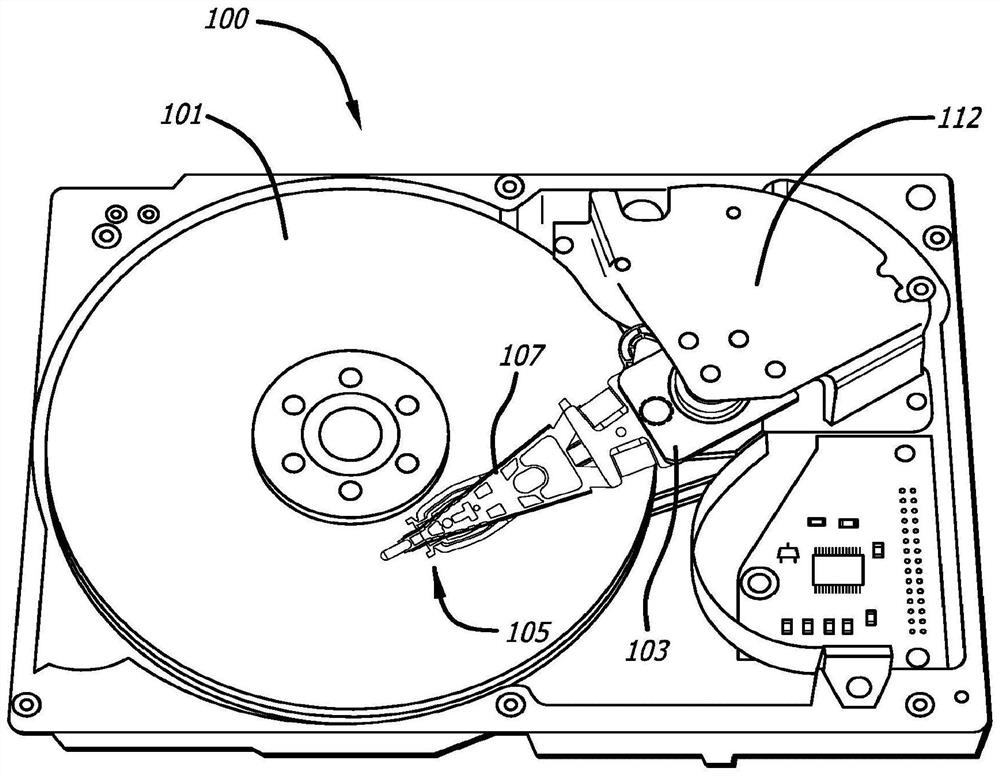
The small linear motion of the PZT thus results in a relatively large radial motion of the read / write head
Method used
Image
Click on the blue label to locate the original text in one second.
Reading with bidirectional positioning of images and text.
Examples
Embodiment Construction
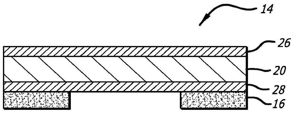
[0074] Figure 7 is a side cross-sectional view of a PZT microactuator assembly 114 with a constraining layer 130 incorporated thereon, in accordance with one embodiment of the present invention. Consistent with the orientation shown in the figures, the side of the PZT that is bonded to the suspension will be referred to as the bottom side 129 of the PZT 114, and the side of the PZT away from the side from which the PZT is bonded will be referred to as the bottom side 129 of the PZT 114. 127 for the top side. According to the present invention, one or more constraining layers or constraining elements 130 are bonded to the top side 127 of the microactuator PZT element 120 . The constraining layer 130 preferably comprises a rigid and elastic material, such as stainless steel, and is preferably bonded directly to the top surface 127 of the PZT element 120 including its top electrode 126, or the SST material itself can be used as the top electrode, thus eliminating the need for a...
PUM
Property
Measurement
Unit
length
aaaaa
aaaaa
thickness
aaaaa
aaaaa
thickness
aaaaa
aaaaa
Abstract
A multilayer piezoelectric microactuator assembly has at least one polarized and active piezoelectric layer and one polarized but passive piezoelectric layer. This polarized but passive layer acts as a constraining layer against expansion or contraction of the first piezoelectric layer, thereby reducing or eliminating bending of the component when installed in the environment, thereby increasing the effective stroke length of the component. Polarizing only a single layer induces stress in the device; thus, polarizing two piezoelectric layers even though only one layer will be active in use reduces the stress in the device and thus increases reliability.
Description
[0001] Cross References to Related Applications [0002] This application is a continuation-in-part of U.S. Patent Application No. 15 / 055,618, filed February 28, 2016, which is U.S. Patent Application No. 14 / 672,122, filed March 28, 2015 (now Patent No. 9,330,698), which is a continuation-in-part of U.S. Patent Application No. 14 / 214,525 (now Patent No. 9,117,468) filed March 14, 2014, which was claimed on March 14, 2013. Priority to U.S. Provisional Patent Application No. 61 / 802,972, filed September 18, and U.S. Provisional Patent Application No. 61 / 877,957, filed September 14, 2013. Application No. 14 / 672,122 is also a continuation-in-part of U.S. Patent Application No. 14 / 566,666, filed December 10, 2014 (now Patent No. 9,330,694), which claims U.S. Provisional Interest in Patent Application No. 62 / 061,074. Application No. 14 / 672,122 also claims the benefit of U.S. Provisional Patent Application No. 62 / 085,471, filed November 28, 2014. All of these applications are incorpo...
Claims
Application Information
Patent Timeline
Application Date:The date an application was filed.
Publication Date:The date a patent or application was officially published.
First Publication Date:The earliest publication date of a patent with the same application number.
Issue Date:Publication date of the patent grant document.
PCT Entry Date:The Entry date of PCT National Phase.
Estimated Expiry Date:The statutory expiry date of a patent right according to the Patent Law, and it is the longest term of protection that the patent right can achieve without the termination of the patent right due to other reasons(Term extension factor has been taken into account ).
Invalid Date:Actual expiry date is based on effective date or publication date of legal transaction data of invalid patent.

