Multi-Layer PZT Microactuator Having A Poled But Inactive PZT Constraining Layer

A micro-actuator, electrode technology, applied in the configuration/installation of the recording head, the installation/connection of the transducing head relative to the arm part, etc.

Active Publication Date: 2018-02-13
MAGNECOMP
View PDF14 Cites 3 Cited by
  • Summary
  • Abstract
  • Description
  • Claims
  • Application Information

AI Technical Summary

Problems solved by technology

The small linear motion of the PZT thus results in a relatively large radial motion of the read / write head

Method used


Image

  • Multi-Layer PZT Microactuator Having A Poled But Inactive PZT Constraining Layer
  • Multi-Layer PZT Microactuator Having A Poled But Inactive PZT Constraining Layer
  • Multi-Layer PZT Microactuator Having A Poled But Inactive PZT Constraining Layer

Examples


Embodiment Construction

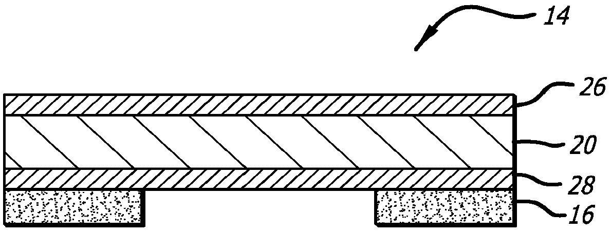
[0074] Figure 7 is a side cross-sectional view of a PZT microactuator assembly 114 with a constraining layer 130 incorporated thereon, in accordance with one embodiment of the present invention. Consistent with the orientation shown in the figures, the side of the PZT that is bonded to the suspension will be referred to as the bottom side 129 of the PZT 114, and the side of the PZT away from the side from which the PZT is bonded will be referred to as the bottom side 129 of the PZT 114. 127 for the top side. According to the present invention, one or more constraining layers or constraining elements 130 are bonded to the top side 127 of the microactuator PZT element 120 . The constraining layer 130 preferably comprises a rigid and elastic material, such as stainless steel, and is preferably bonded directly to the top surface 127 of the PZT element 120 including its top electrode 126, or the SST material itself can be used as the top electrode, thus eliminating the need for a...


PUM

PropertyMeasurementUnit
lengthaaaaaaaaaa
thicknessaaaaaaaaaa
thicknessaaaaaaaaaa

Abstract

A multi-layer piezoelectric microactuator assembly has at least one poled and active piezoelectric layer and one poled but inactive piezoelectric layer. The poled but inactive layer acts as a constraining layer in resisting expansion or contract of the first piezoelectric layer thereby reducing or eliminating bending of the assembly as installed in an environment, thereby increasing the effectivestroke length of the assembly. Poling only a single layer would induce stresses into the device; hence, polling both piezoelectric layers even though only one layer will be active in use reduces stresses in the device and therefore increases reliability.

Description

[0001] Cross References to Related Applications [0002] This application is a continuation-in-part of U.S. Patent Application No. 15 / 055,618, filed February 28, 2016, which is U.S. Patent Application No. 14 / 672,122, filed March 28, 2015 (now Patent No. 9,330,698), which is a continuation-in-part of U.S. Patent Application No. 14 / 214,525 (now Patent No. 9,117,468) filed March 14, 2014, which was claimed on March 14, 2013 Priority to U.S. Provisional Patent Application No. 61 / 802,972, filed September 18, and U.S. Provisional Patent Application No. 61 / 877,957, filed September 14, 2013. Application No. 14 / 672,122 is also a continuation-in-part of U.S. Patent Application No. 14 / 566,666, filed December 10, 2014 (now Patent No. 9,330,694), which claims U.S. Provisional Interest in Patent Application No. 62 / 061,074. Application No. 14 / 672,122 also claims the benefit of U.S. Provisional Patent Application No. 62 / 085,471, filed November 28, 2014. All of these applications are incorpor...

Claims


Application Information

Patent Timeline
Patent Type & Authority Applications(China)
IPC IPC(8): G11B5/48
CPCG11B5/483
Inventor 余坤祺D·格莱斯张泷P·哈恩
Owner MAGNECOMP
Why Eureka
Try Eureka