Protection device for hanging hook of crane

A technology of protective devices and cranes, which is applied in the directions of safety devices, transportation and packaging, and load hanging components, etc., which can solve the problems of poor protection effect and achieve the effect of simple structure and full use of space

Inactive Publication Date: 2018-04-20
弘毅天承知识产权股份有限公司
View PDF0 Cites 3 Cited by
  • Summary
  • Abstract
  • Description
  • Claims
  • Application Information

AI Technical Summary

Problems solved by technology

[0005] In order to solve technical problems such as the poor protection effect of existing crane hook protection devices, the purpose of the present invention is to provide a protection device for crane hooks

Method used


Image

  • Protection device for hanging hook of crane

Examples


Embodiment 1

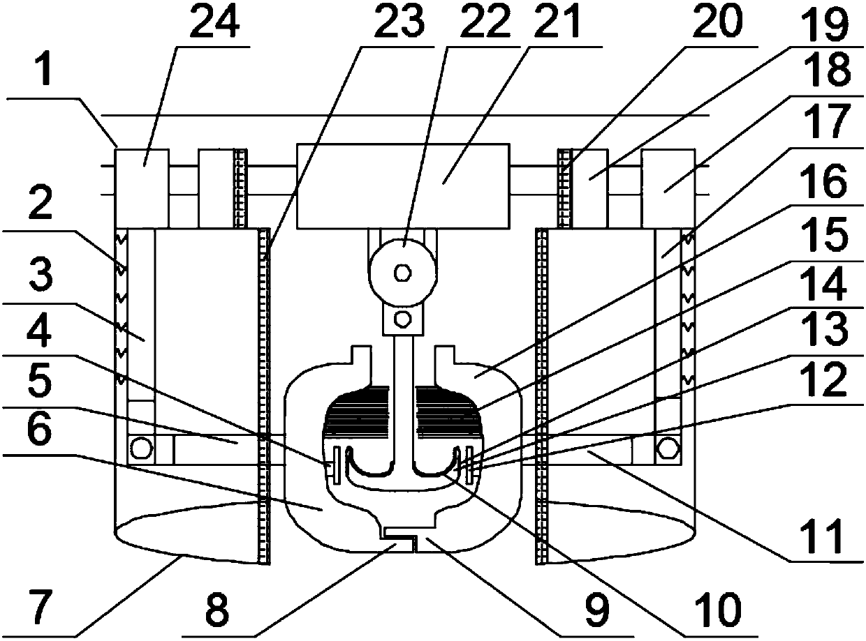
[0027] Such as figure 1 As shown, this embodiment provides a protective device for crane hooks, including crane beam 1, hook slider 21, pulley 22, double hook 13, slider A 24, slider B 18 and arc protection Set 7, a hook slider 21 is set on the crane beam 1, a pulley 22 is arranged under the hook slider 21, a double hook 13 is arranged under the pulley 22, and sliders are symmetrically arranged at both ends of the hook slider 21 A 24 and slider B 18, the bottom of slider A 24 and slider B 18 are riveted and fixed with an arc-shaped protective cover 7, and the bottom of the slider A 24 is also provided with a telescopic link A 3, and the telescopic link A 3 A telescopic link a 5 is hingedly connected, the end of the telescopic link a 5 is provided with a hemispherical protective cover A 6, and the bottom of the slider B 18 is also provided with a telescopic link B 17, and the telescopic link B 17 is hingedly connected with a telescopic link b 11, the end of the telescopic link...

Embodiment 2

[0030] Such as figure 1 As shown, the present embodiment is further optimized on the basis of embodiment 1, and the specific implementation scheme is as follows:

[0031] A spring group 2 is arranged between the outer wall of the telescopic connecting rod A 3 and the telescopic connecting rod B 17 and the inner wall of the arc-shaped protective sleeve 7 .

[0032] In this embodiment, when the telescopic link A and the telescopic link B are controlled to rise and fall, vibration will be generated. A spring group is arranged between the outer wall of the rod B and the inner wall of the arc-shaped protective sleeve, and the contraction elastic protection of the spring is used to play the role of shock absorption.

Embodiment 3

[0034] Such as figure 1 As shown, the present embodiment is further optimized on the basis of embodiment 1, and the specific implementation scheme is as follows:

[0035] Both the inner wall of the hemispherical protective cover A 6 and the hemispherical protective cover B 16 are provided with a fixed rod 4 , and a magnetic block 12 is provided at the end of the fixed rod 4 .

[0036] Both ends of the double hooks 13 are provided with magnetic spacers 14 that cooperate with the magnetic blocks 12 .

[0037] In this embodiment, when the double hooks of the crane enter the inner cavity of the hemispherical protective sheath A and the top openings of the hemispherical protective sheath B, the magnetic pads at both ends of the double hooks are connected with the magnetic blocks at the end of the fixed rod respectively. Attract each other, firmly fix the double hooks in the inner cavity of the hemispherical protective cover, and prevent the double hooks from rotating in the inner ...


PUM


Abstract

The invention discloses a protective device for a crane hook, relates to the technical field of crane equipment, and is used to solve technical problems such as the poor protective effect of the existing crane hook protective device, including a crane beam, a hook slider, a pulley, a double Hook, slider A, slider B and arc protective cover, hook slider is set on the beam of the crane, slider A and slider B are symmetrically arranged at both ends of the hook slider, slider A and slider B The bottom is riveted to fix the arc-shaped protective cover, the bottom of the slider A is equipped with a telescopic link A, the telescopic link A is hingedly connected with the telescopic link a, the end of the telescopic link a is provided with a hemispherical protective cover A, and the bottom of the slider B is provided with a telescopic link B, the telescopic connecting rod B is hingedly connected with the telescopic connecting rod b, the end of the telescopic connecting rod b is provided with a hemispherical protective cover B, the bottom of the hemispherical protective cover A is provided with a magnetic block A, and the bottom of the hemispherical protective cover B is provided with a magnetic block B, the present invention The structure is simple, and the protective cover is set to prevent the end of the hook from being broken due to excessive impact or shaking of the hook.

Description

technical field [0001] The invention relates to the technical field of crane equipment, in particular to a protection device for a crane hook. Background technique [0002] The crane hook is an appliance used to lift heavy objects. When the crane is hoisting, the heavy object is hung on the crane hook, and the lifting of the crane is used to drive the heavy object to move to the designated position. However, the existing crane The hook is usually not equipped with a protective device. When lifting heavy objects, it relies on its own weight to maintain the balance of the lifting. However, for large objects with an unstable center of gravity, it is difficult to control the center of gravity when lifting, which causes the center of gravity to change during the lifting process. The phase falls off, causing the crane hook to shake, which is likely to cause accidents. [0003] When the hook is not in use, the hook is often put away and hung in the air. After a long period of wind...

Claims


Application Information

Patent Timeline
Patent Type & Authority Applications(China)
IPC IPC(8): B66C1/34B66C15/00
CPCB66C1/34B66C15/00
Inventor 赵红昌雍海燕严芳芳陈伊苒曹月琴
Owner 弘毅天承知识产权股份有限公司
Why Eureka
Try Eureka