Intelligent garage stable operation device

A technology of stable operation and intelligent garage, applied in the field of garage, can solve problems such as lifting seat drop, unstable brake, flexibility limitation, etc. Effect

Inactive Publication Date: 2018-09-11
广东锐牛科技有限公司
View PDF11 Cites 8 Cited by
  • Summary
  • Abstract
  • Description
  • Claims
  • Application Information

AI Technical Summary

Problems solved by technology

[0003] The existing three-dimensional garage is driven by a single power source during operation, so that when the power source is in a state, the whole body cannot continue to move, and the flexibility of use is limited. At the same time, the existing three-dimensional garage uses brake shoes for braking and protection during operation. Worn brake pads can easily lead to unstable brakes and cause the lifting seat to fall

Method used


Image

  • Intelligent garage stable operation device
  • Intelligent garage stable operation device
  • Intelligent garage stable operation device

Examples


Embodiment 1

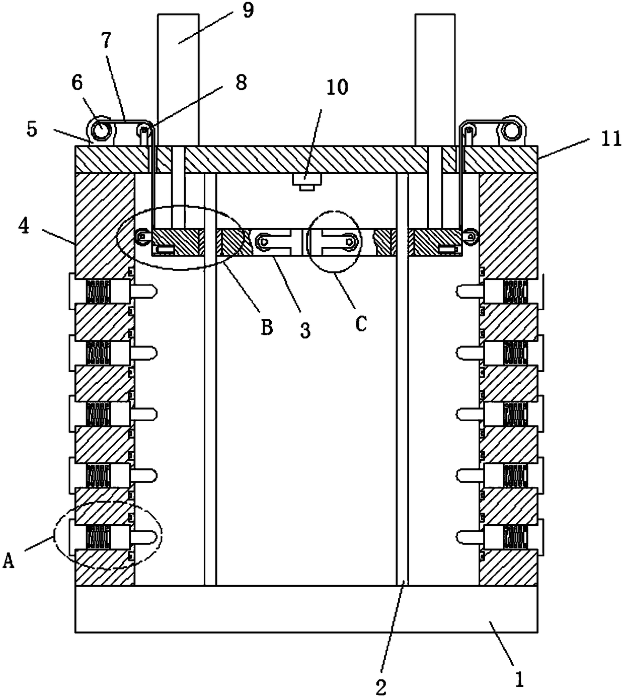
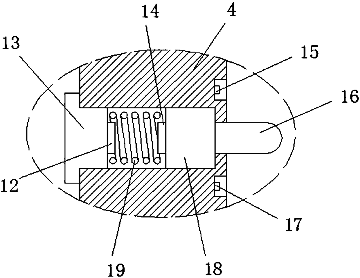
[0024] refer to figure 1 , figure 2 and image 3 , a smart garage operation stabilization device, comprising a fixed base 1, the top ends of the fixed base 1 are fixed with a support base 4, the side edge of the support base 4 is provided with installation holes arranged equidistantly along the height direction of the support base 4, and the installation The inside of the hole is slidingly sleeved with a slide block 18, one end of the slide block 18 is fixed with a positioning post 16, the other end of the slide block 18 is equipped with a second electromagnetic chuck 14, and one end of the mounting hole is threadedly connected with a threaded post 13, the threaded post The first electromagnetic chuck 12 is installed on the end close to the slider 18 on the 13, the inside of the mounting hole is sleeved with a spring 19, and the side edge of the support seat 4 is provided with the first grooves and the first grooves arranged alternately at equal distances along the height di...

Embodiment 2

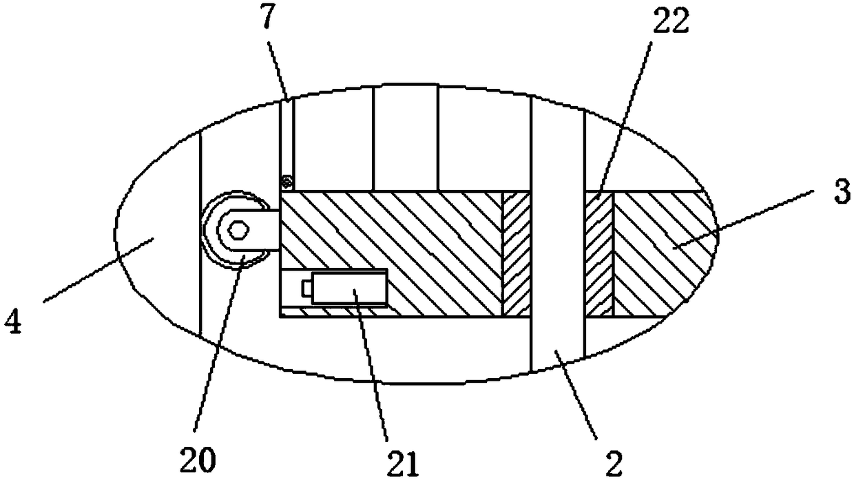
[0029] refer to figure 1 , figure 2 , image 3 and Figure 4 , a smart garage operation stabilization device, comprising a fixed base 1, the top ends of the fixed base 1 are fixed with a support base 4, the side edge of the support base 4 is provided with installation holes arranged equidistantly along the height direction of the support base 4, and the installation The inside of the hole is slidingly sleeved with a slide block 18, one end of the slide block 18 is fixed with a positioning post 16, the other end of the slide block 18 is equipped with a second electromagnetic chuck 14, and one end of the mounting hole is threadedly connected with a threaded post 13, the threaded post The first electromagnetic chuck 12 is installed on the end close to the slider 18 on the 13, the inside of the mounting hole is sleeved with a spring 19, and the side edge of the support seat 4 is provided with the first grooves and the first grooves arranged alternately at equal distances along ...


PUM


Abstract

The invention discloses an intelligent garage stable operation device. The device comprises a fixing base, support bases are fixed to the two ends of the top of the fixing base, mounting holes arranged at equal intervals are formed in the side edges of the supporting bases in the height direction of the support bases, sliding blocks are slidably sleeved with the mounting holes, a locating column is fixed to one end of each sliding block, a second electromagnetic chuck is installed at the other end of each sliding block, a threaded columns is in threaded connection with one end of each mountinghole, a first electromagnetic chuck is installed at the end, close to the corresponding sliding block, of each threaded column, springs are sleeved with the mounting holes, first grooves and second grooves which are alternatively arranged at equal intervals are formed in the side edges of the support based in the height direction of the support bases, rising induction blocks are installed in thefirst grooves, and falling induction blocks are installed in the second grooves. Accordingly, a double-power-source structure is adopted, operation is stable, the very good limiting anti-falling effect is achieved, and operation is safe and reliable.

Description

technical field [0001] The invention relates to the technical field of garages, in particular to an intelligent garage operation stabilization device. Background technique [0002] Mechanical three-dimensional garage: The entire parking facility that uses machinery to access and park vehicles is called a mechanical parking garage. The mechanical parking garage that is stored in three dimensions is called a mechanical three-dimensional parking garage. It is mainly a multi-plane three-dimensional garage. The plane parking garage is the core, through the unified management, monitoring and PLC control of the garage through the computer, that is, the host computer, to change the spatial position of the parking space, so that the parking space can be transformed from space to plane, thereby realizing the function of multi-level plane parking. [0003] The existing three-dimensional garage is driven by a single power source during operation, so that when the power source is in a st...

Claims


Application Information

Patent Timeline
Patent Type & Authority Applications(China)
IPC IPC(8): E04H6/18E04H6/42
CPCE04H6/18E04H6/188E04H6/42
Inventor 陈翔
Owner 广东锐牛科技有限公司
Why Eureka
Try Eureka