Thrusters in the magnetic field, braking and/or power generation devices in the magnetic field

A thruster and magnetic field technology, which is applied in the field of braking and/or power generation devices, can solve problems such as application limitations, difficulty in generating large propulsion, and low magnetic field strength in the earth's or interstellar space.

Inactive Publication Date: 2018-12-18
SHENZHEN DANMING TECH CO LTD
View PDF0 Cites 3 Cited by
  • Summary
  • Abstract
  • Description
  • Claims
  • Application Information

AI Technical Summary

Problems solved by technology

[0002] Due to the low strength of the geomagnetic field or the magnetic field in interstellar space, it is difficult for propellers in the prior art to generate propulsion by using the geomagnetic field or the interstellar space magnetic field to generate large propulsion, resulting in the inability to fully utilize the geomagnetic field or space. The use of magnetic fields or interstellar space magnetic fields to achieve propulsion has been greatly limited in application, and a new design needs to be made

Method used


Image

  • Thrusters in the magnetic field, braking and/or power generation devices in the magnetic field
  • Thrusters in the magnetic field, braking and/or power generation devices in the magnetic field
  • Thrusters in the magnetic field, braking and/or power generation devices in the magnetic field

Examples


Embodiment 1

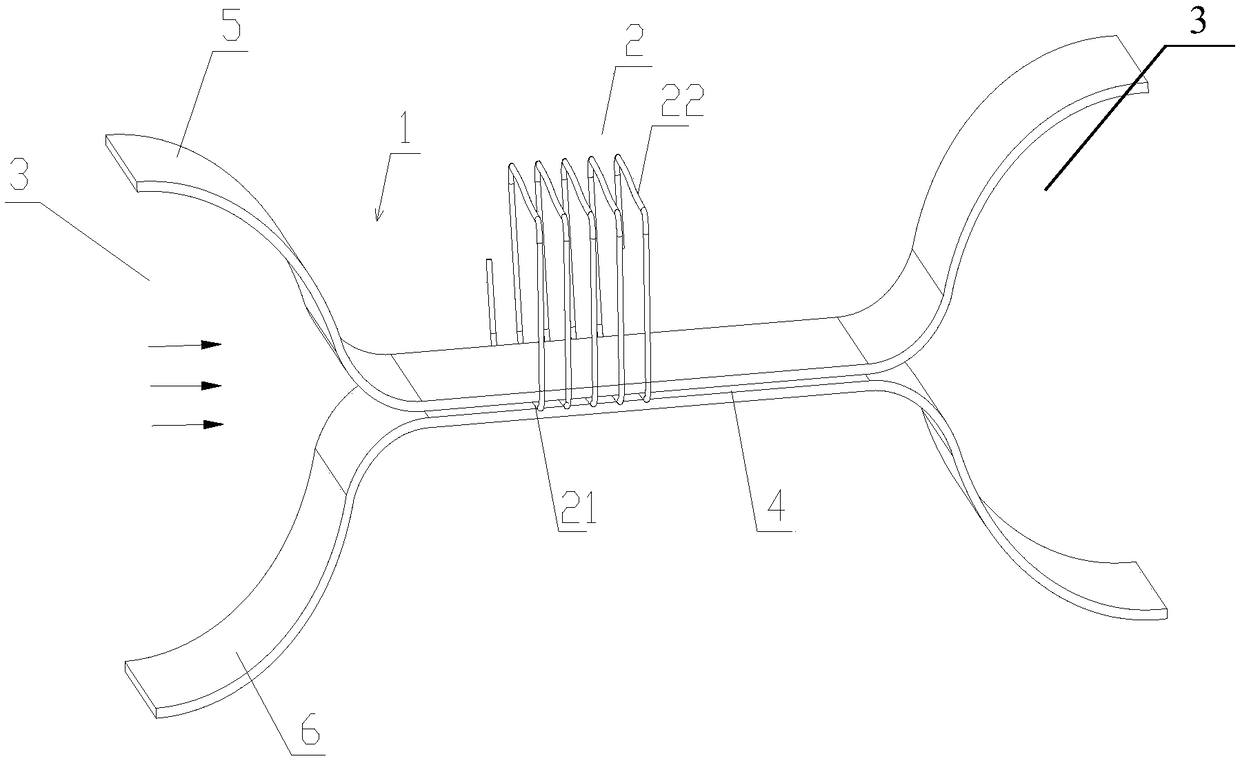
[0085] Please refer to figure 1 , figure 1 It is a structural schematic diagram of a propeller disclosed in the first embodiment of the present invention.

[0086] As shown in the figure, in this embodiment, the propeller provided by the present invention has a magnetic field gathering part 1 and a conductor that can be energized. In this embodiment, the conductor is a wire 2 (the wire 2 in each of the following embodiments can be energized), wherein, the magnetic field gathering part 1 for enhancing the external magnetic field has left and right ( figure 1 The external magnetic field path that runs through the middle, left, and right directions), the external magnetic field path includes the closed path 3 and the reinforced path 4, and the distance between the closed path 3 in space from the upper and lower to the middle (the middle of the upper and lower directions) gradually increases from one end to the other end Narrow ( figure 1 In the middle, the closing channel 3 at...

Embodiment 2

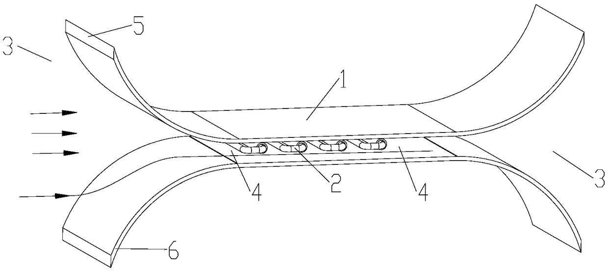
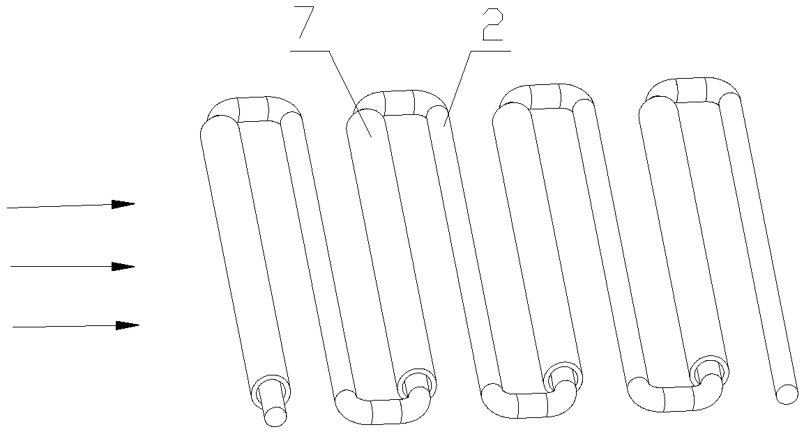
[0093] Please refer to figure 2 , image 3 , figure 2 It is a structural schematic diagram of a propeller disclosed in the second embodiment of the present invention; image 3 yes figure 2 Schematic diagram of the structure of the conductor shown in .

[0094] As shown in the figure, in this embodiment, the propeller provided by the present invention has a magnetic field concentrating part 1 and a conductor, wherein the magnetic field concentrating part 1 for enhancing the magnetic field has left and right ( figure 2 The external magnetic field path that runs through the left and right directions), the external magnetic field path includes the closed path 3 and the reinforced path 4, and the space between the closed path 3 is gradually narrowed from one end to the other end from the top and bottom to the middle ( figure 2 In the middle, the closing channel 3 at the right end gradually narrows from right to left, and the closing channel 3 at the left end gradually narr...

Embodiment 3

[0104] Please refer to Figure 4 , Figure 5 , Figure 4 It is a structural schematic diagram of a propeller disclosed in the third embodiment of the present invention; Figure 5 yes Figure 4 Cutaway view of the propeller shown.

[0105] As shown in the figure, this embodiment is obtained by further improvement and / or simplification on the basis of embodiment one or embodiment two. The closing channel 3 at the other end is removed, and such a structure can also achieve the purpose of the present invention. Please refer to the above for other structures, and the description will not be repeated here.

[0106] Preferably, the external magnetic field path can be a path closed on both sides, that is, the two sides of the upper guide 5 and the lower guide 6 are respectively provided with a lateral guide 8 for closing the lateral space, and the material of the lateral guide 8 is selected Available materials for the upper guide 5.


PUM


Abstract

A thruster includes a magnetic field collecting member and an electrically energizable conductor, characterized by, the magnetic field collecting member is provided with a left-right penetrating external magnetic field passage for enhancing the external magnetic field, The external magnetic field path comprises at least a retraction path and an enhancement path, wherein the retraction path is narrowed directly or spatially from above and / or between the lower direction, the retraction path is narrowed from one end to the other end, and the enhancement path is a path after the retraction path isnarrowed or a postponement path after the retraction path is narrowed. The thruster has greater propulsion force, and can be in various forms, the structure is simple, and can effectively overcome the shortcomings of the existing thrusters.

Description

technical field [0001] The invention relates to the technical field of propellers, in particular to propellers that generate propulsion in magnetic fields such as the earth's magnetic field, cosmic space magnetic field, or interstellar space magnetic field, and braking and / or power generation devices in the magnetic field. Background technique [0002] Due to the low strength of the geomagnetic field or the magnetic field in interstellar space, it is difficult for propellers in the prior art to generate propulsion by using the geomagnetic field or the interstellar space magnetic field to generate large propulsion, resulting in the inability to fully utilize the geomagnetic field or space. The use of magnetic fields or interstellar space magnetic fields to achieve propulsion has been greatly limited in application, and a new design needs to be made. [0003] Therefore, how to overcome the shortcomings of existing propellers is a technical problem to be solved by those skill...

Claims


Application Information

Patent Timeline
Patent Type & Authority Applications(China)
IPC IPC(8): H02K41/00H02K1/06
CPCH02K41/00H02K1/06
Inventor 李丹
Owner SHENZHEN DANMING TECH CO LTD
Why Eureka
Try Eureka