An automatic detection method and system for a camera module

A camera module and automatic detection technology, applied in image communication, television, electrical components, etc., can solve the problems of wrong way of inputting camera module model configuration parameters, error-prone identification of camera module model, low efficiency, etc.

Active Publication Date: 2019-06-11
CHENGDU GUOKE MICROELECTRONICS CO LTD
View PDF6 Cites 9 Cited by
  • Summary
  • Abstract
  • Description
  • Claims
  • Application Information

AI Technical Summary

Problems solved by technology

[0005] This application provides an automatic detection method and system for a camera module to solve the problem of error-prone and low-efficiency identification of the cam

Method used


Image

  • An automatic detection method and system for a camera module
  • An automatic detection method and system for a camera module
  • An automatic detection method and system for a camera module

Examples


Embodiment Construction

[0040] In order to enable those skilled in the art to better understand the technical solutions in the present application, the technical solutions in the embodiments of the present application will be clearly and completely described below in conjunction with the drawings in the embodiments of the present application. Obviously, the described The embodiments are only some of the embodiments of the present application, not all of them. Based on the embodiments in this application, all other embodiments obtained by persons of ordinary skill in the art without creative efforts shall fall within the scope of protection of this application.

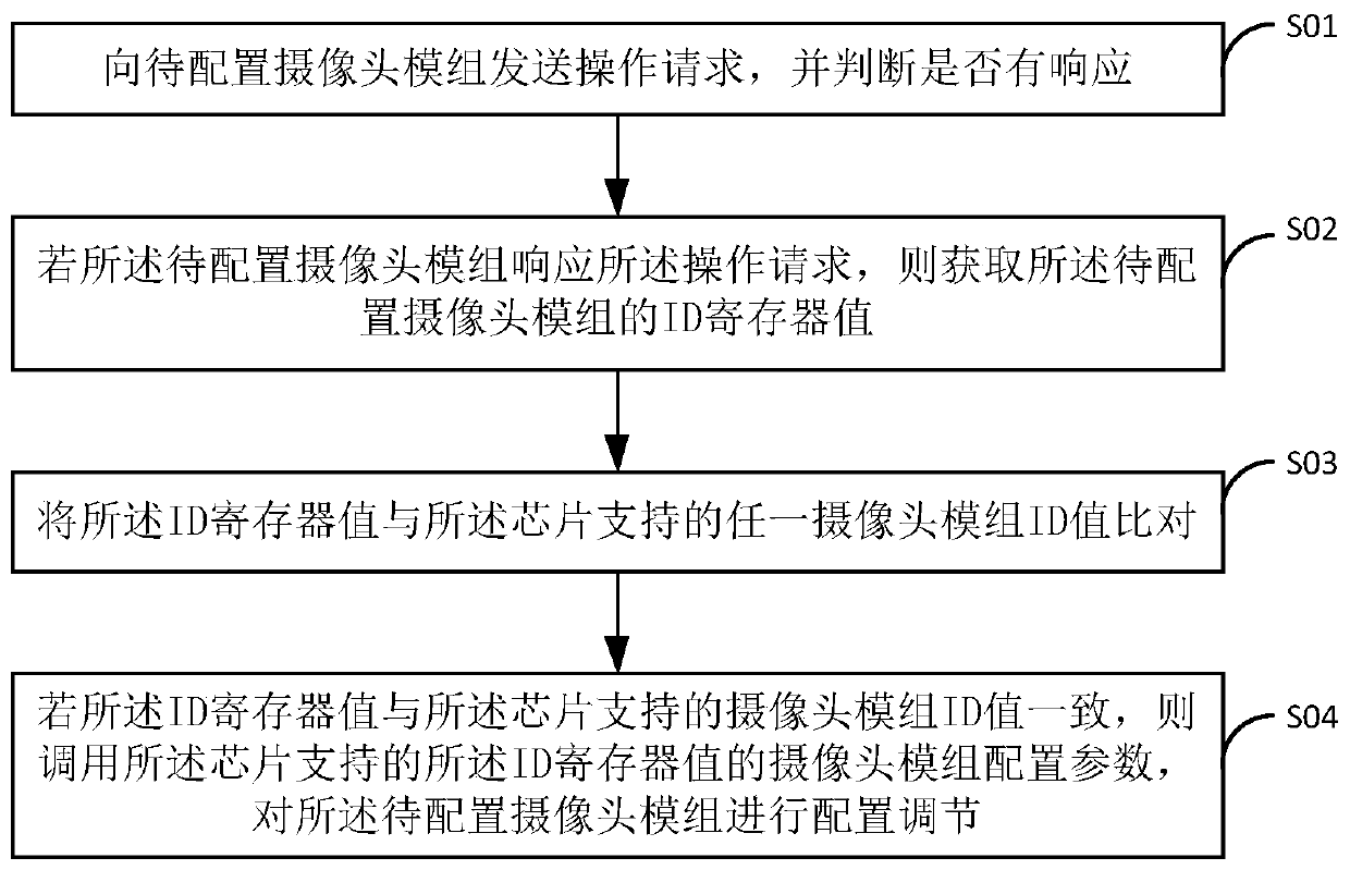
[0041] see figure 1 , is a schematic flowchart of an automatic detection method for a camera module provided by an embodiment of the present invention. In this application, the configuration parameters of all camera module models supported by the chip are preset in the chip software driver, and the configuration parameters include: initializ...


PUM


Abstract

The invention discloses an automatic detection method and system for a camera module, wherein the configuration parameters of the types of all camera modules supported by a chip software driver are preset in the chip software driver. The method comprises the steps of sending an operation request to a to-be-configured camera module, and judging whether a response exists or not; If the to-be-configured camera module responds to the operation request, obtaining an ID register value of the to-be-configured camera module; comparing the ID register value with the ID value of any camera module supported by the chip; and if the ID register value is consistent with the ID value of the camera module supported by the chip, calling a camera module configuration parameter of the ID register value supported by the chip, and carrying out configuration adjustment on the to-be-configured camera module. According to the method and the device, the type of the camera module accessed to the camera input system can be automatically identified, more camera modules are supported, and meanwhile, the preset configuration parameters are called for configuration, so that the error rate is reduced, and the working production efficiency is improved.

Description

technical field [0001] The present application relates to the technical field of camera control, in particular to a camera module automatic detection method and system. Background technique [0002] Camera, also known as computer camera, computer eye and electronic eye, is a video input device, which is widely used in video conferencing, telemedicine and real-time monitoring. In order to expand the imaging range of images and improve user experience, dual-camera technology is widely used in mobile phones, driving recorders, monitoring and other fields. [0003] At present, in the development of dual-camera software and hardware, it is carried out for the situation where the camera module model is known, but in the software and hardware development of the chip design manufacturer, it is hoped to support as many camera module models as possible, and increase the number of chip-to-camera module models. selectivity. So that different developers may use different camera modules...

Claims


Application Information

Patent Timeline
IPC IPC(8): H04N17/00
Inventor 鲍超王斌
Owner CHENGDU GUOKE MICROELECTRONICS CO LTD
Why Eureka
Try Eureka