A three-degree-of-freedom piezoelectric pointing adjustment device and platform control method for keeping power off

An adjustment device and platform control technology, applied in the direction of generators/motors, piezoelectric effect/electrostrictive or magnetostrictive motors, electrical components, etc., can solve the life loss of piezoelectric devices, the limitation of rotation angle range, and life loss etc. to achieve the effect of self-compensation for installation errors, low requirements for location layout, and reduced power consumption

Active Publication Date: 2021-01-29
HARBIN INST OF TECH
View PDF7 Cites 0 Cited by
  • Summary
  • Abstract
  • Description
  • Claims
  • Application Information

AI Technical Summary

Problems solved by technology

Driven by a traditional motor, the entire mechanism is bulky, the transmission chain is long, the control is complex, and the weight is heavy, which is not conducive to the application to the space field that requires small weight and small volume.
The patent application with the publication number CN109889084A proposes a piezoelectric-driven ultra-precision feed and attitude adjustment device and its excitation method. The driving platform of this invention application cannot achieve power-off maintenance after the attitude adjustment, and the piezoelectric drive unit needs Always energize to keep the adjusted platform position and angle unchanged, which will reduce the life of the piezoelectric device; the patent application with the publication number CN108054512A proposes a high-torque anti-jamming antenna pointing mechanism for deep space exploration. It is necessary to use the brake to energize and output the holding torque to realize the holding of the mechanism, but it cannot realize self-locking when the power is off; the patent application with the application number 201710583870. One-stage lever amplification, the micro-displacement magnification is limited, resulting in the limitation of the output external rotation angle range, and the lever mechanism is an asymmetric structure, which has a high requirement for the position layout of the piezoelectric stack, which has a key impact on the magnification
It can be seen that the adjustable angle range of the existing piezoelectric drive mechanism is small, and it needs to be powered on all the time during work, without the self-locking function when power is off, resulting in waste of electric energy.

Method used


Image

  • A three-degree-of-freedom piezoelectric pointing adjustment device and platform control method for keeping power off
  • A three-degree-of-freedom piezoelectric pointing adjustment device and platform control method for keeping power off
  • A three-degree-of-freedom piezoelectric pointing adjustment device and platform control method for keeping power off

Examples


Embodiment 1

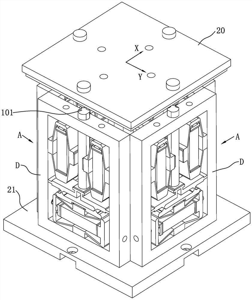
[0057] Example 1, see Figure 5-Figure 7 As shown, the driving piezoelectric stack 9 of each adjustment mechanism A in this embodiment is arranged horizontally and perpendicular to the length direction of the two braking piezoelectric stacks 12, and the braking piezoelectric stack 12 horizontal arrangement;

[0058] Each adjustment mechanism A includes a push rod 1, a driving mechanism, a braking mechanism and a support body D;

[0059] The drive mechanism includes a drive piezoelectric stack 9 and a micro-displacement amplification structure B;

[0060] The braking mechanism includes two braking triangular amplification structures 11 and two braking piezoelectric stacks 12;

[0061] A braking piezoelectric stack 12 is arranged in each braking triangular amplification structure 11, and the opposite output ends of the two braking triangular amplification structures 11 are fixedly connected to the support body D, and the phases of the two braking triangular amplification struc...

Embodiment 2

[0064] Example 2, such as Figure 8 As shown, the difference between this embodiment and Embodiment 1 is that the micro-displacement amplifying structure B is a driving triangular amplifying structure 5, and a driving piezoelectric stack 9 is installed in the driving triangular amplifying structure 5, and the driving triangular amplifying structure 5 and The driving piezoelectric stacks 9 are respectively connected to the support body D, and the output end of the driving triangular amplifying structure 5 is in contact with the bottom end of the ejector rod 1 . The working principle is the same as that of Embodiment 1.

Embodiment 3

[0065] Example 3, such as Figure 9 As shown, the difference between this embodiment and Embodiments 1 and 2 is that the driving piezoelectric stack 9 is vertically arranged and perpendicular to the length direction of the two braking piezoelectric stacks 12, and the braking piezoelectric stack The stack 12 is arranged horizontally; the micro-displacement amplifying structure B is a lever amplifying structure 4, the lever amplifying structure 4 is connected with the support body D, and one end of the driving piezoelectric stack 9 is in contact with the input end of the lever amplifying structure 4, driving the piezoelectric The other end of the stack 9 is connected to the support body D, and the output end of the lever amplification structure 4 is in contact with the bottom end of the push rod 1 . The lever amplifying structure 4 is a symmetrical design. Such as Figure 15As shown, this embodiment is a power-off maintenance orthogonal adjustment mechanism, and its working pr...


PUM


Abstract

A three-degree-of-freedom piezoelectric pointing adjustment device and platform control method for power-off maintenance, a piezoelectric drive adjustment device and method, the device includes a platform, a base, and three or four adjustment mechanisms; each adjustment mechanism includes a push rod , driving mechanism, braking mechanism and support body; the upper end of the ejector rod is fixed on the platform, and a universal flexible hinge is processed on the ejector rod, the universal flexible hinge is located between the upper part of the support body and the platform, and the support body is fixed on the base The steps of the method include: 1. assembling the adjustment mechanism, the platform and the base; 2. releasing the self-locking state of the ejector rod; The device of the invention has a compact structure, is used in a space environment, and operates stably and reliably. The platform can realize adjustment of three degrees of freedom, and can meet the application requirements of the space environment.

Description

technical field [0001] The invention relates to a piezoelectric drive adjustment device and method, in particular to a power-off maintaining three-degree-of-freedom piezoelectric pointing adjustment device and a platform control method, belonging to the field of piezoelectric precision drive. Background technique [0002] With the rapid development of science and technology, there is an urgent need for ultra-precision positioning and pointing mechanisms in the fields of optics, semiconductors, and mechanical processing, especially in the space field. At present, deep space exploration, laser communication, and laser ranging are developing rapidly. The high-precision pointing of the platform is an important Indicators often need to use a high-precision pointing adjustment mechanism to adjust the platform pointing. [0003] There are two main forms of pointing adjustment mechanism at present, one is the pointing adjustment mechanism driven by the transmission motor, and the ot...

Claims


Application Information

Patent Timeline
Patent Type & Authority Patents(China)
IPC IPC(8): H02N2/04H02N2/02H02N2/06
CPCH02N2/028H02N2/043H02N2/06
Inventor 黎明王伟祥曲建俊
Owner HARBIN INST OF TECH
Why Eureka
Try Eureka