Damping connection fitting

A technology for connecting hardware and damping, applied in the installation of electrical components, cables, overhead installation, etc., can solve the problems of unreachable and the influence of wire connection strength, and achieve the effect of improving work quality and stability.

Inactive Publication Date: 2022-01-28
黄秋宇
View PDF0 Cites 0 Cited by
  • Summary
  • Abstract
  • Description
  • Claims
  • Application Information

AI Technical Summary

Problems solved by technology

[0002] Iron or aluminum metal accessories widely used in power transmission lines are collectively referred to as fittings. Most fittings need to bear large tension during operation, and some of them must also ensure good electrical contact. Fittings such as wire clips and protective fittings that are connected and combined into a hanging or strain-resistant string (group) are called connecting fittings, but after the existing connecting fittings are connected to two wires, when the wires are pulled, the pulling force directly acts on the two wires. The connection will affect the connection strength of the wire for a long time. In addition, when the wire is subjected to tension, the existing connection fittings cannot offset the tension, which cannot meet the requirements of today's use. Therefore, we propose a damping connection. Goldware

Method used


Image

  • Damping connection fitting
  • Damping connection fitting
  • Damping connection fitting

Examples


Embodiment Construction

[0024] The following will clearly and completely describe the technical solutions in the embodiments of the present invention with reference to the accompanying drawings in the embodiments of the present invention. Obviously, the described embodiments are only some, not all, embodiments of the present invention.

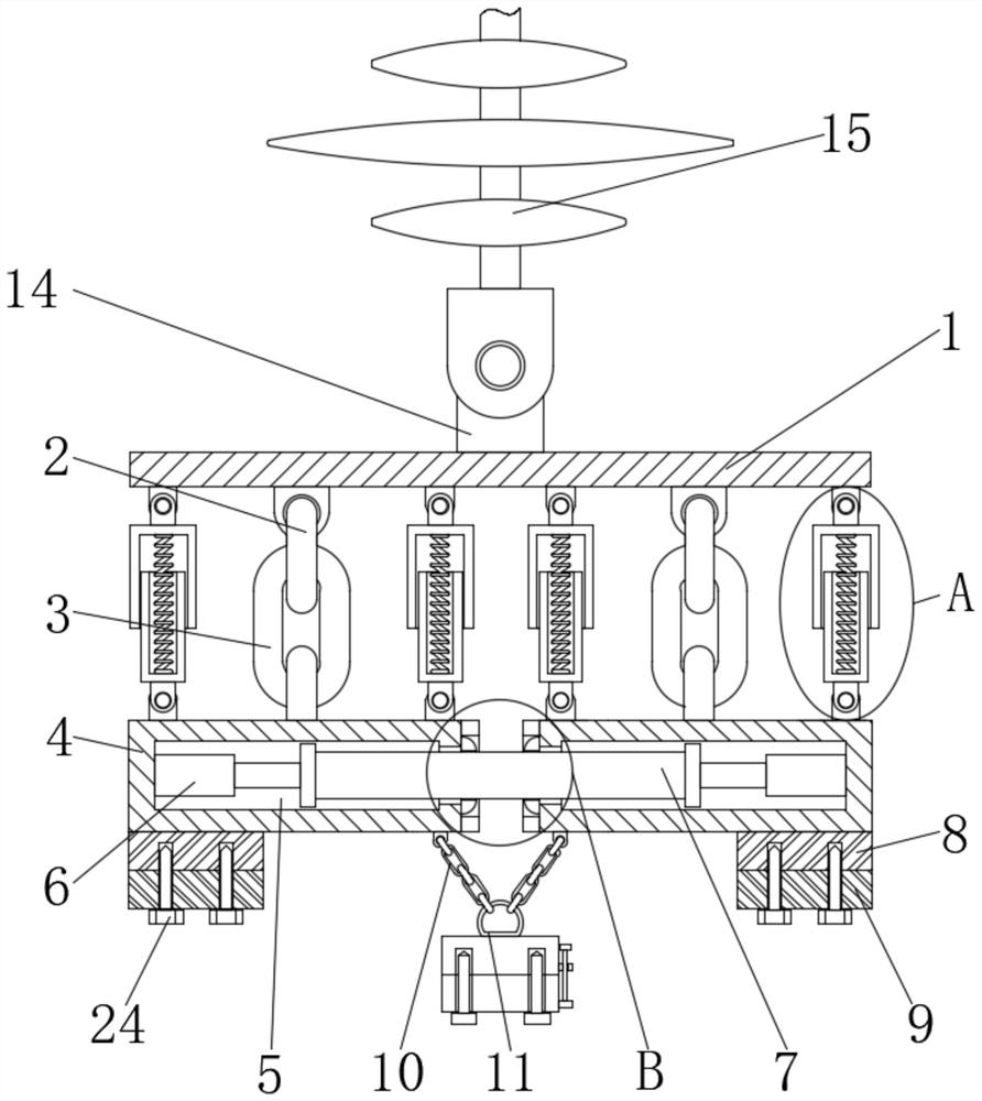
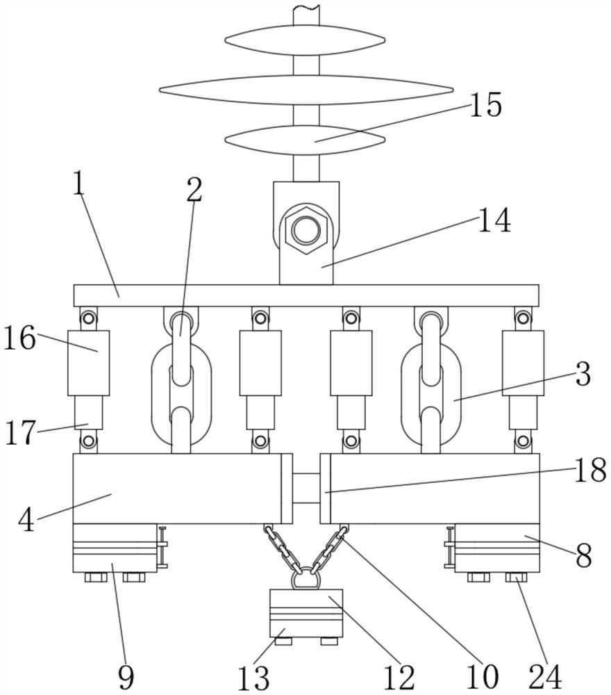
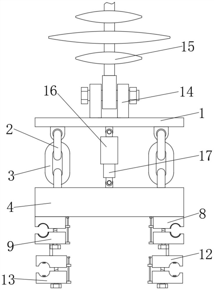
[0025] see Figure 1 to Figure 7 , the present invention provides a technical solution: a damping connection hardware, including a suspension base 1, four first pull rings 2 are sleeved on the bottom of the suspension base 1, and the four first pull rings 2 are respectively sleeved The second pull ring 3 is connected, and the bottom ends of the two second pull rings 3 are sleeved with a suspension plate 4, and the bottom ends of the other two second pull rings 3 are sleeved with another suspension plate 4, and the two suspension plates 4 are sleeved. The interior of the suspension plate 4 is provided with sliding grooves 5, and the inner cavity of one sliding groove ...


PUM


Abstract

The invention discloses a damping connection fitting, and relates to the technical field of connection fittings. The damping connection fitting comprises a suspension base, the bottom of the suspension base is sleeved with four first pull rings, the four first pull rings are sleeved with second pull rings respectively, the bottom ends of the two second pull rings are sleeved with one suspension plate, the bottom ends of the other two second pull rings are sleeved with the other suspension plate, sliding grooves are formed in the two suspension plates, a sliding column is clamped in the inner cavity of one sliding groove, and one end of the sliding column is clamped in the inner cavity of the other sliding groove. According to the damping connection fitting, when an electric wire is subjected to tensile force, the tensile force is directly transmitted to the suspension plates through the fixed base and the fixed extrusion base, the two suspension plates are driven to move towards the two sides, air rods generate extrusion force, the suspension plates are pulled to move towards the inner side through the counter-acting force of the air rods, the received tensile force is offset, and the function of eliminating the pulling force applied to the electric wire is realized.

Description

technical field [0001] The invention relates to the technical field of connecting fittings, in particular to a damping connecting fitting. Background technique [0002] Iron or aluminum metal accessories widely used in power transmission lines are collectively referred to as fittings. Most fittings need to bear large tension during operation, and some of them must also ensure good electrical contact. Fittings such as wire clips and protective fittings that are connected and combined into a hanging or strain-resistant string (group) are called connecting fittings, but after the existing connecting fittings are connected to two wires, when the wires are pulled, the pulling force directly acts on the two wires. The connection will affect the connection strength of the wire for a long time. In addition, when the wire is subjected to tension, the existing connection fittings cannot offset the tension, which cannot meet the requirements of today's use. Therefore, we propose a damp...

Claims


Application Information

Patent Timeline
IPC IPC(8): H02G7/05H02G7/04H02G7/12
CPCH02G7/05H02G7/04H02G7/125
Inventor 黄秋宇黄钦
Owner 黄秋宇
Why Eureka
Try Eureka