Cylindrical pipeline cleaning equipment

A pipe cleaning, cylindrical technology, applied in the direction of cleaning hollow objects, cleaning methods and utensils, chemical instruments and methods, etc., can solve the problems of poor cleaning effect and large floor space, so as to speed up the flow rate of water and improve work efficiency Efficiency, enhanced cleaning effect

Pending Publication Date: 2022-07-15
陈书华
View PDF0 Cites 0 Cited by
  • Summary
  • Abstract
  • Description
  • Claims
  • Application Information

AI Technical Summary

Problems solved by technology

[0004] In order to overcome the shortcomings of the existing cleaning equipment that occupy a large area and have poor cleaning effects, the technical problem to be solved is to provide a cylindrical pipeline cleaning equipment that occupies a small area and has a good cleaning effect

Method used


Image

  • Cylindrical pipeline cleaning equipment
  • Cylindrical pipeline cleaning equipment
  • Cylindrical pipeline cleaning equipment

Examples


Embodiment 1

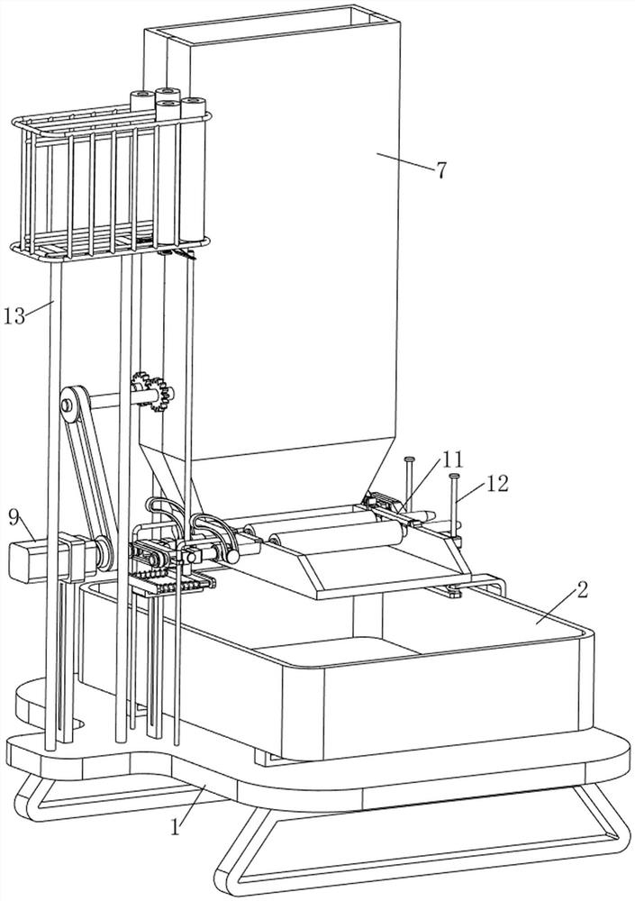
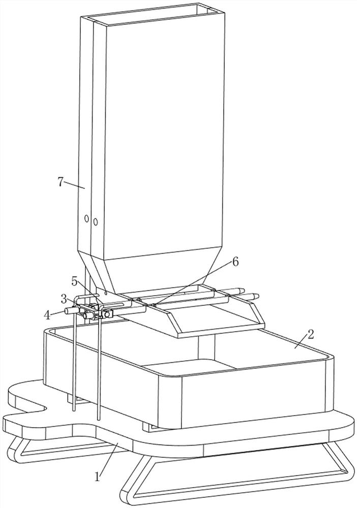
[0070] A cylindrical pipe cleaning equipment, such as Figure 1-Figure 5 As shown, it includes a bottom plate 1, a collection frame 2, a first support frame 3, a first rotating shaft 4, a placement column 5, a fixing ring 6, a water tank 7, a water discharge mechanism 8 and a rotating mechanism 9, and the top of the bottom plate 1 is provided with a collection frame 2 , a first support frame 3 is arranged in the middle of the front side of the top of the bottom plate 1, the upper part of the first support frame 3 is symmetrically arranged with a first rotating shaft 4, and the rear side of the first rotating shaft 4 is rotatably provided with a placing column 5, and the placing column 5 A fixing ring 6 is provided on the front side, a water tank 7 is provided in the middle of the top left side of the bottom plate 1, the placing column 5 is in contact with the water tank 7, a water discharge mechanism 8 is provided at the lower part of the water tank 7, and a rotating mechanism ...

Embodiment 2

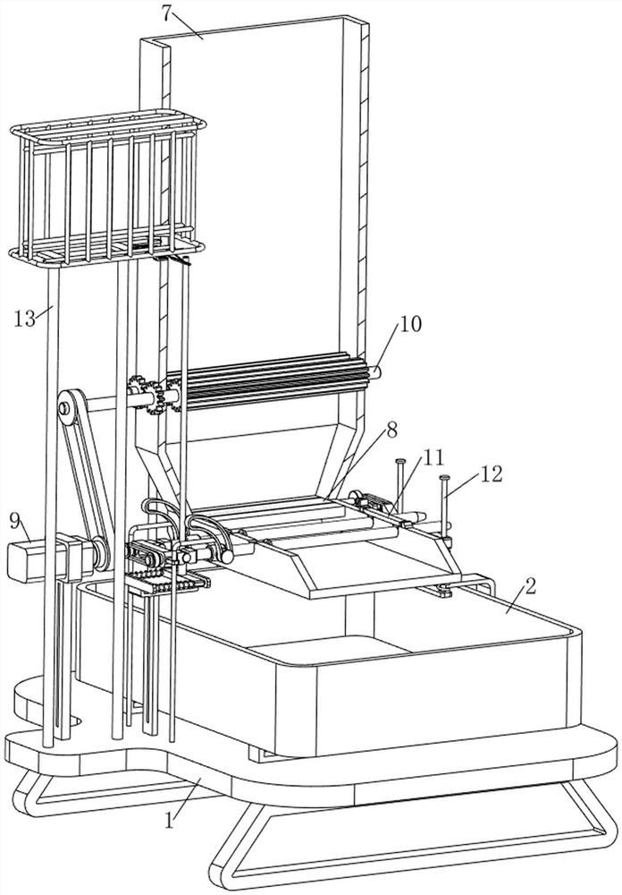
[0075] On the basis of Example 1, as Figure 6-Figure 10 As shown, it also includes a pressing mechanism 10. The pressing mechanism 10 includes a fourth rotating shaft 1000, a roller 1001, a transmission belt 1002, a full gear 1003 and a pressing gear 1004. The lower part of the water tank 7 is provided with a fourth rotating shaft 1000 symmetrically rotating left and right. , the fourth rotating shaft 1000 is located above the second rotating shaft 80 , the front side of the fourth rotating shaft 1000 on the right side and the rear side of the third rotating shaft 92 are provided with rollers 1001 , a transmission belt 1002 is wound between the rollers 1001 , and the front side of the fourth rotating shaft 1000 All gears 1003 are provided with all gears 1003 meshing with each other, and pressurizing gears 1004 are provided on the fourth rotating shaft 1000 .

[0076] When people start the motor 91 , the output shaft of the motor 91 drives the third rotating shaft 92 to rotate...


PUM


Abstract

The invention relates to cleaning equipment, in particular to cylindrical pipeline cleaning equipment. The technical problem to be solved is to provide the cylindrical pipeline cleaning equipment which is small in occupied area and good in cleaning effect. The cylindrical pipeline cleaning equipment comprises a bottom plate and a collecting frame, and the collecting frame is arranged at the top of the bottom plate; the first supporting frame is arranged in the middle of one side of the top of the bottom plate; the first rotating shafts are symmetrically and rotationally arranged at the upper part of the first support frame; the placement columns are rotationally arranged on one sides of the first rotating shafts; the fixing rings are arranged on one sides of the placing columns; the water tank is arranged in the middle of one side of the top of the bottom plate and makes contact with the containing column. And the water drainage mechanism is arranged at the lower part of the water tank. Through cooperation of the water discharging mechanism and the rotating mechanism, the round pipe can be automatically driven to rotate, then the round pipe is automatically cleaned, and time and labor are saved.

Description

technical field [0001] The invention relates to a cleaning device, in particular to a cylindrical pipe cleaning device. Background technique [0002] Pipelines are widely used, mainly used in water supply, drainage, heating, gas supply, long-distance transportation of oil and natural gas, agricultural irrigation, hydraulic engineering and various industrial installations. After the pipeline is made, it needs to be cleaned before it can be sold. [0003] The existing cleaning equipment occupies a large area and needs to occupy a large space, which is inconvenient for people to carry and use, and when in use, people need to manually load and unload materials, which is more troublesome and leads to low work efficiency. , In addition, there is no limit to the circular pipe, which cannot be cleaned in all directions, and the cleaning effect is not good. Therefore, a cylindrical pipe cleaning equipment with a small footprint and good cleaning effect is designed. SUMMARY OF THE I...

Claims


Application Information

Patent Timeline
Patent Type & Authority Applications(China)
IPC IPC(8): B08B9/02B08B13/00
CPCB08B9/02B08B13/00
Inventor 陈书华
Owner 陈书华
Why Eureka
Try Eureka