High efficiency and easy diffusive negative ion generator

A negative ion generator and ion emission head technology, applied in the field of electronics, can solve the problems of rising failure rate, poor use effect, and breakdown of turns in transformers, etc., to solve the problem of low ion escape efficiency, improve use effect, and eliminate the need for The effect of short circuit protection

Inactive Publication Date: 2003-10-01
西安海利德负离子科技有限公司
View PDF0 Cites 13 Cited by
  • Summary
  • Abstract
  • Description
  • Claims
  • Application Information

AI Technical Summary

Problems solved by technology

[0004] The structure of these products is composed of a casing, a core circuit, an anion emitter and a power plug. The high-voltage generator of the core part of the core circuit is a traditional wire-wound transformer, which requires a high voltage ratio of the transformer. At this time, There are high requirements for the insulation strength of the primary winding and the secondary winding of the transformer and the insulation strength between the secondary turns, which makes the processing process complicated, the cost increases, the failure rate increases during use, and often leads to the breakdown between turns in the transformer. wear, short circuit, and even cause catastrophic consequences such as burning; and now the surface of the general casing is insulated (including plastic casings and metal casings that become non-conductors that are insulated from other parts due to coating treatment) negatively charged The ions will be absorbed by the casing with positive potential on the escape path. When the negative ions gather to a certain extent, a negatively charged barrier will be formed to prevent the negative ions from escaping, so that the negative ions produced by the instrument are limited to the instrument. Inside the casing, it cannot reach the air, and the casing only protects the movement. The high-concentration (positive) negative ions generated by the negative ion generator inside the casing can only escape out of the casing by means of diffusion or fan blowing. , where most of the negative ions are blocked or absorbed by the shell and attenuated, the actual use effect is poor

Method used


Image

  • High efficiency and easy diffusive negative ion generator
  • High efficiency and easy diffusive negative ion generator
  • High efficiency and easy diffusive negative ion generator

Examples


Embodiment Construction

[0020] In order to understand the present invention more clearly, the present invention will be further described in detail below in conjunction with the accompanying drawings.

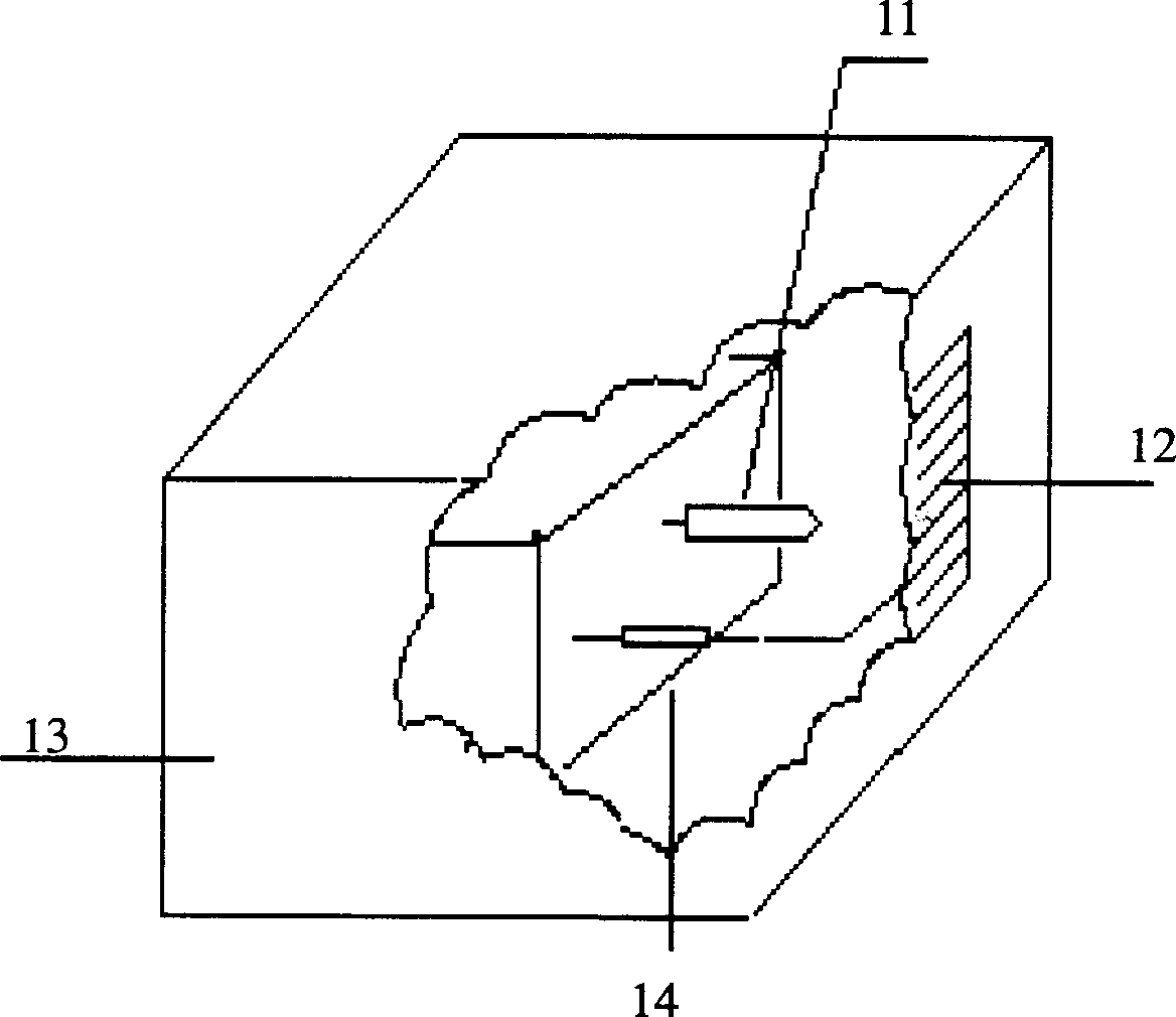
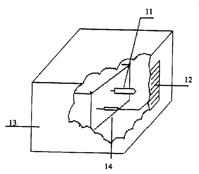
[0021] As we all know, the working principle of negative ion generator is: use high voltage electric field to ionize air to generate (positive) ions, and the working voltage required for the generation of ions is from thousands of volts to tens of thousands of volts. In order to ensure personal safety and avoid possible contact with high-voltage parts, the negative (positive) ion generator is generally placed in an airtight casing, and the negative ions produced by the negative ion generator escape through a specially set window.

[0022] As shown in Fig. 1, the present invention is made up of casing, movement circuit, ion emission head 11, discharge resistance 14, casing is made up of casing 13 and conductive protection grid 12, is connected on the conductive protection grid 12 At a certain potential...


PUM


Abstract

A high-efficiency and easy-diffusion anion generator has a machine casing consisting of shell body and conductive guard grid and a core circuit including power supply circuit which is composed of AC power supply and DC power supply to be exchanged to each other through switch and oscillation booster circuit which is composed of oscillation circuit booster circuit and multistage voltage-multiplying circuit. The features of the generator are as: A special conductive guard grid is applied to the generator for exchanging power supply from AC to DC, a chip piezoelectric ceramic transformer is applied to the booster circuit for boosting, and there is a protective resistance connected between the mulstiage voltage-multiplying circuit and the anion emission head.

Description

[0001] Field [0002] The invention belongs to the field of electronic technology, and relates to a negative ion generator which generates a large amount of negative ions by ionizing air with a high-voltage electric field generated by a sheet piezoelectric ceramic transformer and has a conductive protection grid. Background technique [0003] Negative ion generators can purify the air environment, generate fresh air, and have auxiliary therapeutic functions for people’s health and certain diseases. At present, many countries in the world have successively researched and produced them. Developed countries such as the United States, France, Japan, and Russia have already used them more commonly; Relevant manufacturers have developed and produced products with better performance, such as Xinghe Electric Appliance Factory in Zhongshan City, Guangdong Province, Chaoyang Sanlian Textile Electronic Equipment Research Institute and other units have successively produced negative ion ge...

Claims


Application Information

Patent Timeline
Patent Type & Authority Applications(China)
IPC IPC(8): H01T23/00H05C3/00
CPCH01T23/00
Inventor 陈耀刚侯志俊
Owner 西安海利德负离子科技有限公司
Why Eureka
Try Eureka