Small-particle negative ion generator

A negative ion generator and small particle size technology, applied in the electronic field, can solve problems such as poor use effect, increased failure rate, transformer breakdown, etc., and achieve the effect of improved use effect, fewer components and simple structure

Inactive Publication Date: 2017-03-15
诸城市寰润环保科技有限公司
View PDF0 Cites 1 Cited by
  • Summary
  • Abstract
  • Description
  • Claims
  • Application Information

AI Technical Summary

Problems solved by technology

Relevant manufacturers in China have developed and produced products with better performance. The structures of these products are composed of casings, core circuits, negative ion emitters and power plugs. The high-voltage generators of the core part of the core circuit are traditional wire-wound Transformer requires a high voltage ratio of the transformer. At this time, there are high requirements for the insulation strength between the primary winding and the secondary winding of the transformer and the insulation strength between the secondary turns, which makes the processing process complicated, the cost increased, and the failure rate during use. Rise will often lead to disastrous consequences such as breakdown, short circuit, and even burning between turns in the transformer; and now the surface of the general casing is insulated (including plastic casings and metal casings due to coating treatment) become a non-conductor insulated from other parts), negatively charged ions will be absorbed by the casing with positive potential on the escape path, and when the negative ions gather to a certain extent, a negatively charged barrier will be formed. Prevent the escape of negative ions, so that the negative ions generated by the instrument are limited to the instrument casing and cannot reach the air. The casing only protects the movement. The high-concentration (positive) negative ions generated by the negative ion generator inside the casing It can only escape out of the shell by means of diffusion or electric fan blowing air, most of the negative ions are blocked or absorbed by the shell and attenuated, and the actual use effect is poor

Method used


Image

  • Small-particle negative ion generator
  • Small-particle negative ion generator

Examples


Embodiment Construction

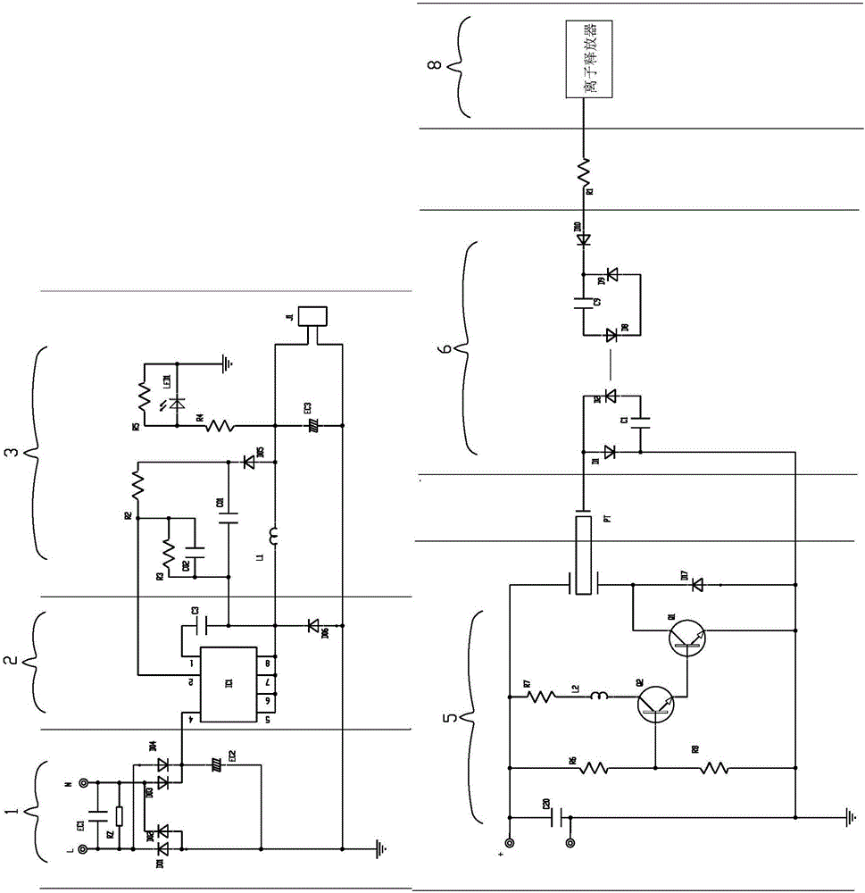
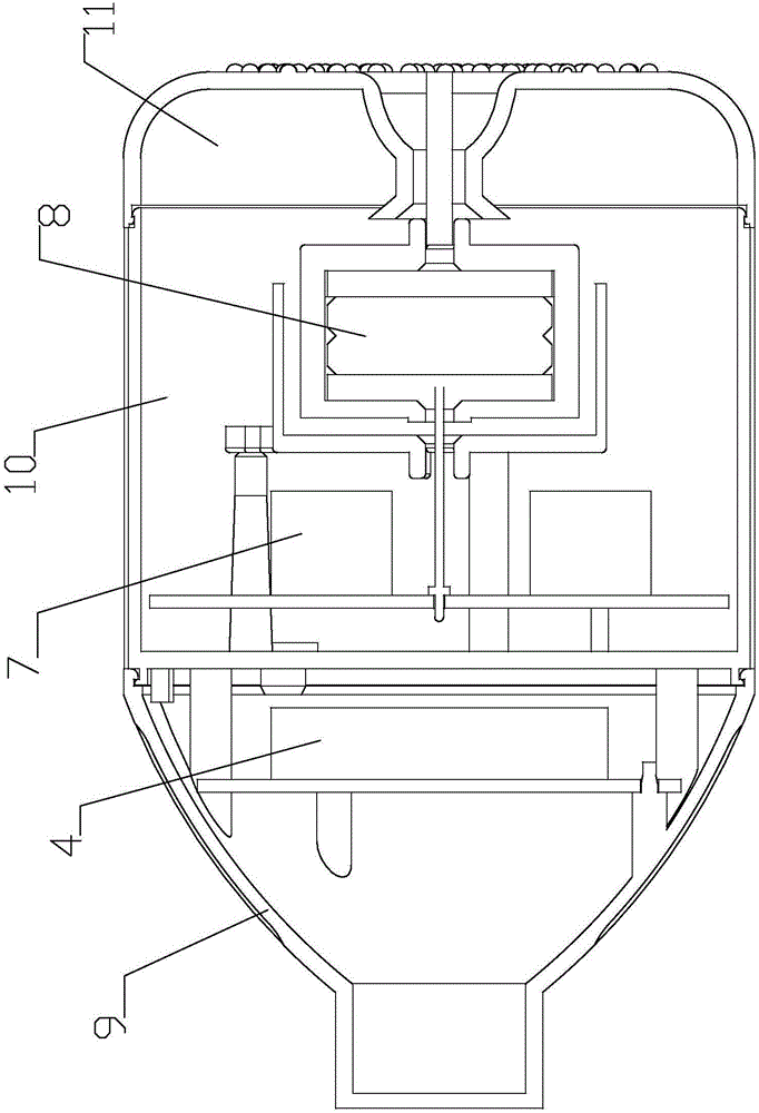
[0016] Such as figure 1 figure 2 As shown, the small particle size negative ion generator is made up of a shell and an internal circuit. The shell is made up of a lower shell 9, a middle shell 10, and an upper shell 11. The lower shell 9 is provided with a rectifier circuit 1, a step-down I circuit 2, a A power supply circuit 4 composed of a voltage sampling circuit 3, a boost circuit 7 composed of an oscillating circuit 5 and a multi-stage voltage doubler circuit 6 is arranged in the middle shell 10, the power supply circuit 4 is connected to the boost circuit 7, and the boost circuit 7 passes through a protection resistor R1, the high-voltage line is connected to the ion releaser 8 in the middle shell 10. The ion releaser 8 is composed of a circuit board, a superconducting sheet, a converter, a discharge needle or a discharge brush, and the ion releaser 8 is a nanofullerene anion releaser;

[0017] The rectifier circuit 1 includes filter capacitors EC1, EC2, resistors RZ,...


PUM


Abstract

The invention discloses a small-particle negative ion generator. The small-particle negative ion generator comprises a shell and an internal circuit, wherein the shell comprises a lower shell, an intermediate shell and an upper shell, a power supply circuit is arranged in the lower shell and comprises a rectification circuit, a buck I circuit and a buck sampling circuit, a boost circuit is arranged in the intermediate shell and comprises an oscillation circuit and a multi-stage voltage doubling circuit, the power supply circuit is connected with the boost circuit, the boost circuit is connected with an ion releaser in the intermediate shell through a resistor R1 and a high-voltage line, and the ion releaser comprises a circuit board, a superconduction sheet, a converter, a discharge needle or a discharge brush and is a nano fullerene negative ion releaser. By the small-particle negative ion generator, the problem of low ion escaping efficiency in an enclosure of an existing ion generator is solved, and the application effect of the negative ion generator is greatly improved.

Description

technical field [0001] The invention relates to the technical field of electronics, in particular to a small-diameter negative ion generator. Background technique [0002] Negative ion generators can purify the air environment, generate fresh air, and have auxiliary therapeutic functions for people's health and certain diseases. At present, many countries in the world have successively researched and produced them, and developed countries such as the United States, France, Japan, and Russia have been widely used. Relevant manufacturers in China have developed and produced products with better performance. The structures of these products are composed of casings, core circuits, negative ion emitters and power plugs. The high-voltage generators of the core part of the core circuit are traditional wire-wound Transformer requires a high voltage ratio of the transformer. At this time, there are high requirements for the insulation strength between the primary winding and the seco...

Claims


Application Information

Patent Timeline
Patent Type & Authority Applications(China)
IPC IPC(8): H01T23/00
CPCH01T23/00
Inventor 张永锋车秀玉李臣锋
Owner 诸城市寰润环保科技有限公司
Why Eureka
Try Eureka