Confocal displacement sensor

a sensor and confocal technology, applied in the field ofconfocal displacement sensors, can solve the problems of difficult to appropriately remove background components, deteriorate measurement accuracy, etc., and achieve the effects of reducing the influence of reflected light, reducing the influence of refractive index matching materials, and being easy to handl

Active Publication Date: 2018-12-25
KEYENCE
View PDF12 Cites 2 Cited by
  • Summary
  • Abstract
  • Description
  • Claims
  • Application Information

AI Technical Summary

Benefits of technology

[0008]The present invention has been devised in view of the circumstances, and an object of the present invention is to provide a confocal displacement sensor that can improve measurement accuracy. In particular, an object of the present invention is to provide a confocal displacement sensor that can improve measurement accuracy for a measurement object having a low reflectance.

Problems solved by technology

Therefore, measurement accuracy is deteriorated.
Therefore, it is difficult to appropriately remove the background component.

Method used


Image

  • Confocal displacement sensor
  • Confocal displacement sensor
  • Confocal displacement sensor

Examples


Embodiment Construction

[0033]An embodiment of the present invention is explained below with reference to the drawings. In this specification, for convenience, a direction of an optical axis of a head unit is explained as an up-down direction. However, a posture and a direction during use of the head unit are not limited.

Confocal Displacement Sensor 1

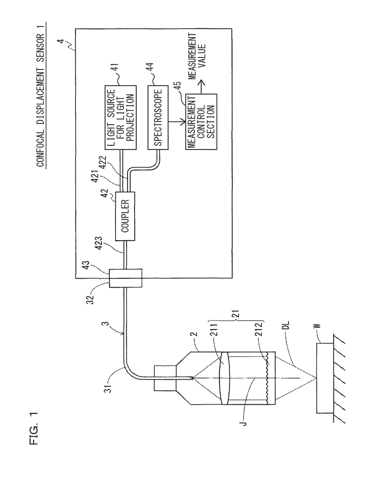
[0034]FIG. 1 is a system diagram showing a configuration example of a confocal displacement sensor 1 according to the embodiment of the present invention. The confocal displacement sensor 1 is an optical measurement device configured by a head unit 2, a fiber cable 3, and a control unit 4. The optical measurement device receives reflected light from a measurement object W when detection light DL is emitted from the head unit 2 and measures displacement of the measurement object W.

[0035]The head unit 2 and the control unit 4 are connected to each other via the fiber cable 3. The fiber cable 3 includes an optical fiber 31 that transmits light for light projectio...


PUM


Abstract

The confocal displacement sensor includes a first optical fiber, to a first incident end of which light for light projection is input, the first optical fiber outputting the light from a first emission end, a second optical fiber, a second incident end of which is disposed to be opposed to the first emission end, the second optical fiber emitting light input via the second incident end from a second emission end, an optical member configured to cause an axial chromatic aberration on detection light emitted via the second emission end and converge the detection light toward the measurement object, a fiber connecting section configured to detachably connect the second incident end to the first emission end, and a refractive index matching material disposed between the first emission end and the second incident end.

Description

CROSS-REFERENCE TO RELATED APPLICATIONS[0001]The present application claims foreign priority based on Japanese Patent Application No. 2017-115555, filed Jun. 13, 2017, the contents of which is incorporated herein by reference.BACKGROUND OF THE INVENTION1. Field of the Invention[0002]The present invention relates to a confocal displacement sensor and, more particularly, to improvement of a confocal displacement sensor that measures displacement of a measurement object using a confocal optical system.2. Description of Related Art[0003]A confocal displacement sensor is an optical measurement device that measures displacement of a measurement object making use of a confocal principle of stopping down received light into reflected light from an image forming surface on which an image of a light source is formed and a phenomenon of an axial chromatic aberration in which a color drift in an optical axis direction occurs in the image of the light source.[0004]The confocal displacement senso...

Claims


Application Information

Patent Timeline
Patent Type & Authority Patents(United States)
IPC IPC(8): G01B11/02G01J3/02
CPCG01B11/026G01J3/0291G01J3/0218G01J3/0208G01B11/02G01B2210/50G01B11/0608
Inventor TAKEI, HIDETOSAKAGUCHI, TOMIKAZU
Owner KEYENCE
Why Eureka
Try Eureka