Wireless power transmission apparatus

a technology of power transmission apparatus and wires, which is applied in the direction of transformers, inductances, transportation and packaging, etc., can solve the problems of degrading increasing and affecting so as to improve the efficiency reduce the range of transmission power amount to be adjusted in the wireless power transmission apparatus, and reduce the realization cost of the wireless power charging system

Active Publication Date: 2019-11-19
LG INNOTEK CO LTD
View PDF38 Cites 0 Cited by
  • Summary
  • Abstract
  • Description
  • Claims
  • Application Information

AI Technical Summary

Benefits of technology

[0007]According to the wireless power transmission apparatus of the disclosure, as a plurality of transmission coils are formed symmetrically to each other, magnetic fields formed by the transmission coils have vertical and horizontal symmetrical shapes. Accordingly, the coupling coefficient between the wireless power transmission apparatus and the wireless power reception apparatus can be constant according to the locations of the wireless power transmission apparatus. Accordingly, the variation range of a transmission power amount to be adjusted in the wireless power transmission apparatus can be reduced, so that the realization cost of the wireless power charging system can be reduced and the efficiency of the wireless power charging system can be improved.

Problems solved by technology

However, as the connector in the electronic device is exposed to the outside, the connector may be contaminated with foreign matters or shorted by moisture.
In this case, connection failure occurs between the connector and the charging device, so that the battery in the electronic device may not be charged with power.
Accordingly, the realization cost of the wireless power charging system may be increased and the efficiency of the wireless power charging system may be degraded.

Method used


Image

  • Wireless power transmission apparatus
  • Wireless power transmission apparatus
  • Wireless power transmission apparatus

Examples


Embodiment Construction

[0028]Hereinafter, embodiments of the disclosure will be more described with reference to accompanying drawings. In this case, it is noted that the same reference numerals are assigned to the same elements as much as possible. In addition, the details of well known functions or configurations that may make the subject matter of the embodiments unclear will be omitted in the following description.

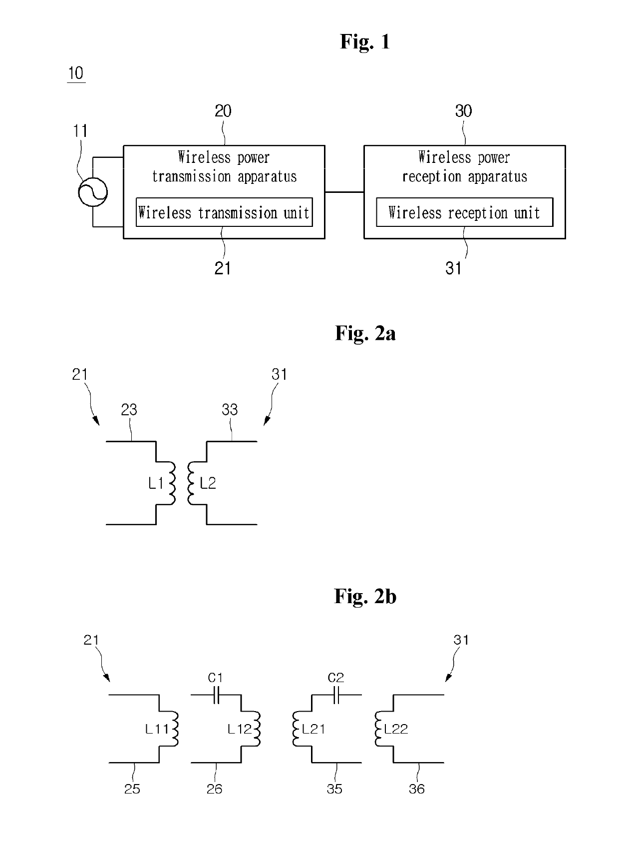
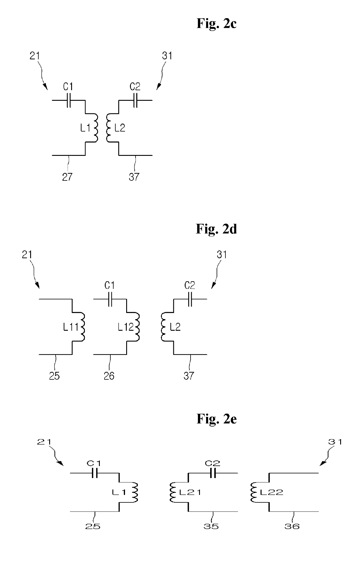
[0029]FIG. 1 is a block diagram showing a typical wireless power charging system, and FIGS. 2a, 2b, 2c, 2d, and 2e are circuit diagrams showing equivalent circuits of a wireless transmission unit and a wireless reception unit showing in FIG. 1.

[0030]Referring to FIG. 1, a typical wireless power charging system 10 includes a wireless power transmission apparatus 20 and a wireless power reception apparatus 30.

[0031]The wireless power transmission apparatus 20 is connected with a power supply 11 to receive power from the power supply 11. In addition, the wireless power transmission apparatus 20...


PUM

PropertyMeasurementUnit
radiusaaaaaaaaaa
radiusaaaaaaaaaa
radiusaaaaaaaaaa

Abstract

A wireless power transmission apparatus can include a member; an upper transmission coil disposed on the member; and first and second terminals disposed in the member, in which the upper transmission coil includes an outer coil part connected to the first terminal and formed in one-turn; a first inner coil part connected to the outer coil part and having a half-turn on a first region of the member; a second inner coil part connected to the first inner coil part and having a half-turn on a second region of the member; a third inner coil part connected to the second inner coil part and having a half-turn on the first region of the member; and a fourth inner coil part connected to the third inner coil part and the second terminal and having a half-turn on the second region of the member, in which the half-turn of the second inner coil part comprises a first rounded corner, a second rounded corner and a third rounded corner, a circular arc of the first rounded corner of the second inner coil part is R 20 mm as a radius of a circle, a circular arc of the second rounded corner of the second inner coil part is R 18.4 mm as a radius of a circle, and a circular arc of the third rounded corner of the second inner coil part is greater than the circular arc of the first and second rounded corners of the second inner coil part.

Description

CROSS-REFERENCE TO RELATED APPLICATIONS[0001]This Application is a Continuation of co-pending U.S. patent application Ser. No. 14 / 831,685 filed on Aug. 20, 2015, which is a Continuation of U.S. patent application Ser. No. 14 / 709,075 filed on May 11, 2015 (now U.S. Pat. No. 9,450,423 issued on Sep. 20, 2016), which claims the priority benefit under 35 U.S.C. § 119(a) to Korean Patent Application Nos. 10-2015-0014965 filed in the Republic of Korea on Jan. 30, 2015, and 10-2014-0131402 filed in the Republic of Korea on Sep. 30, 2014, all of which are hereby expressly incorporated by reference into the present application.BACKGROUND OF THE INVENTIONField of the Invention[0002]The disclosure relates to a wireless power charging system, and more particularly to a wireless power transmission apparatus of a wireless power charging system.Discussion of the Related Art[0003]In general, various electronic devices are equipped with batteries and driven using power charged in the batteries. In t...

Claims


Application Information

Patent Timeline
Patent Type & Authority Patents(United States)
IPC IPC(8): H01F27/42H01F37/00H01F38/00H02J5/00H02J50/23H02J7/00H02J7/02H01F38/14
CPCH02J5/005H02J7/0042H02J50/23H02J7/025H01F38/14H02J50/70H02J50/10H02J50/12H02J50/005H04B5/0087H04B5/0037
Inventor BAE, SU HOYONG, DONG HO
Owner LG INNOTEK CO LTD
Why Eureka
Try Eureka