Dust scanner

a scanner and dust technology, applied in the field of dust scanners, can solve the problems of reducing the efficiency of wet cleaning, unexpectedly leaving dust, and affecting physical and psychological health, so as to reduce the effort of locally performing recleaning because cleaning was not done well, and improve cleaning efficiency.

Active Publication Date: 2022-10-11
KIM JUNG HUI
View PDF12 Cites 0 Cited by
  • Summary
  • Abstract
  • Description
  • Claims
  • Application Information

AI Technical Summary

Benefits of technology

[0009]As described above, according to the present disclosure, light beams advancing straight in parallel to a floor are projected far while being maintained to be low, so foreign substances such as dust, dirt, and the like are clearly identified in the field of view of a cleaner user through the shadows generated by and the light beams reflected from the foreign substances.
[0010]Accordingly, even when a large area is to be cleaned, efforts of locally performing recleaning because cleaning was not done well can be reduced. As a result, cleaning efficiency can be improved.

Problems solved by technology

Periodic cleaning is very important because an unclean environment may adversely affect both physical and psychological health.
However, when cleaning, a cleaner user thinks that debris or dust has been removed with a vacuum cleaner, but finds that dust is unexpectedly left here and there during performing wet cleaning.
Meanwhile, residual dust lowers efficiency of wet cleaning, wherein the reason why the cleaner user is not able to cleanly remove dust with a broom or vacuum cleaner is that small foreign substances such as dust are difficult to see on the floor surface under ceiling lighting from eye level.
However, in cases that an area to be cleaned is quite large or the number of places to be cleaned is quite large, such as offices in a large building, reperforming dry-cleaning becomes a factor that reduces the cleaning efficiency and increases the working time.

Method used


Image

  • Dust scanner
  • Dust scanner
  • Dust scanner

Examples


Embodiment Construction

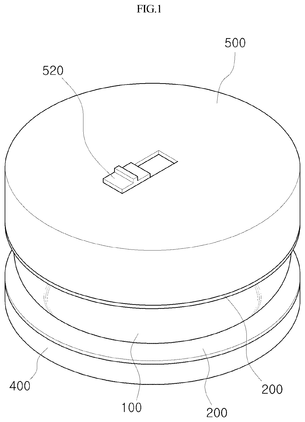
[0019]Proposed in the present disclosure is a dust scanner that allows various foreign substances such as debris, dust, and the like existing on a floor to be clearly identified in a field of view of a cleaner user by projecting light beams at a height adjacent to the floor of an area to be cleaned, the dust scanner including: a plurality of LED lighting components; a transmissive body including a parabolic surface having a vertical cross-section convex toward an outside, formed to be transparent, and configured to transmit the light beams emitted from the plurality of LED lighting components located at an inside thereof to an outside; and blocking plates each closing and sealing a top end and a bottom end between the plurality of LED lighting components and the transmissive body, wherein each of the plurality of LED lighting components is disposed at a focal point of the parabolic surface, the focal point being spaced apart from the transmissive body by a predetermined interval, wh...


PUM


Abstract

Proposed in the present disclosure is a dust scanner allowing various foreign substances existing on a floor to be clearly identified in a field of view of a cleaner user, the dust scanner including: a plurality of LED lighting components; a transmissive body including a parabolic surface having a vertical cross-section convex toward an outside, formed to be transparent, and configured to transmit light beams emitted from the LED lighting components located at an inside thereof to an outside; and blocking plates each closing and sealing a top end and a bottom end between the LED lighting components and the transmissive body, wherein each of the LED lighting components is disposed at a focal point of the parabolic surface, whereby the light beams transmitted to the parabolic surface are projected in parallel to a floor without spreading up and down.

Description

CROSS-REFERENCE TO RELATED APPLICATIONS[0001]This application is the U.S. national stage application of International Patent Application No. PCT / KR2020 / 002614, filed Feb. 24, 2020, which claims the benefit under 35 U.S.C. § 119 of Korean Application No. 10-2019-0024001, filed Feb. 28, 2019, the disclosures of each of which are incorporated herein by reference in their entirety.TECHNICAL FIELD[0002]The present disclosure relates to a dust scanner and, in particular, to a dust scanner capable of improving cleaning efficiency by clearly identifying small foreign substances existing on a floor.BACKGROUND ART[0003]The internal space where people execute business such as desk job, work, or the like or reside should be cleaned regularly to maintain a clean and comfortable environment. Periodic cleaning is very important because an unclean environment may adversely affect both physical and psychological health.[0004]In general, cleaning proceeds in a way using a vacuum cleaner to suck and r...

Claims


Application Information

Patent Timeline
Patent Type & AuthorityPatents(United States)
IPC IPC(8): F21V5/04A47L9/30F21V7/05G02B27/30F21Y107/30F21Y115/10
CPCA47L9/30F21V5/046F21V7/05G02B27/30F21Y2107/30F21Y2115/10F21V33/0044F21W2131/30F21Y2107/40F21S9/02F21V5/043F21L4/027F21K9/00F21V5/04
InventorKIM, JUNG HUI
OwnerKIM JUNG HUI