Stack type optical disk changer

a technology of optical disk changer and stack type, which is applied in the direction of recording carrier contruction details, instruments, data recording, etc., can solve the problems of preventing the movement of the cartridge, the stack type optical disk changer b>10/b> does not have a special device, etc., to prevent the movement of the cartridge and the tray, prevent misoperation and breakage, and maintain the quality of sound or image of the optical disk. , the effect of preventing the movement of th

Inactive Publication Date: 2005-06-30
LG ELECTRONICS INC
View PDF8 Cites 7 Cited by
  • Summary
  • Abstract
  • Description
  • Claims
  • Application Information

AI Technical Summary

Benefits of technology

[0017] Therefore, an object of the present invention is to provide a stack type optical disk changer which can maintain quality of sound or image of an optical disk by efficiently preventing a cartridge and each tray from moving due to external shaking or impact, and which can prevent damages of the optical disk, mis-operations and breakage, by preventing the optical disk from being separated from the tray.

Problems solved by technology

However, the conventional stack type optical disk changer 10 does not have a special device for preventing movement of the cartridge 12 in the reproduction mode or replacement mode of the optical disk.

Method used


Image

  • Stack type optical disk changer
  • Stack type optical disk changer
  • Stack type optical disk changer

Examples


Embodiment Construction

[0038] Reference will now be made in detail to the preferred embodiments of the present invention, examples of which are illustrated in the accompanying drawings.

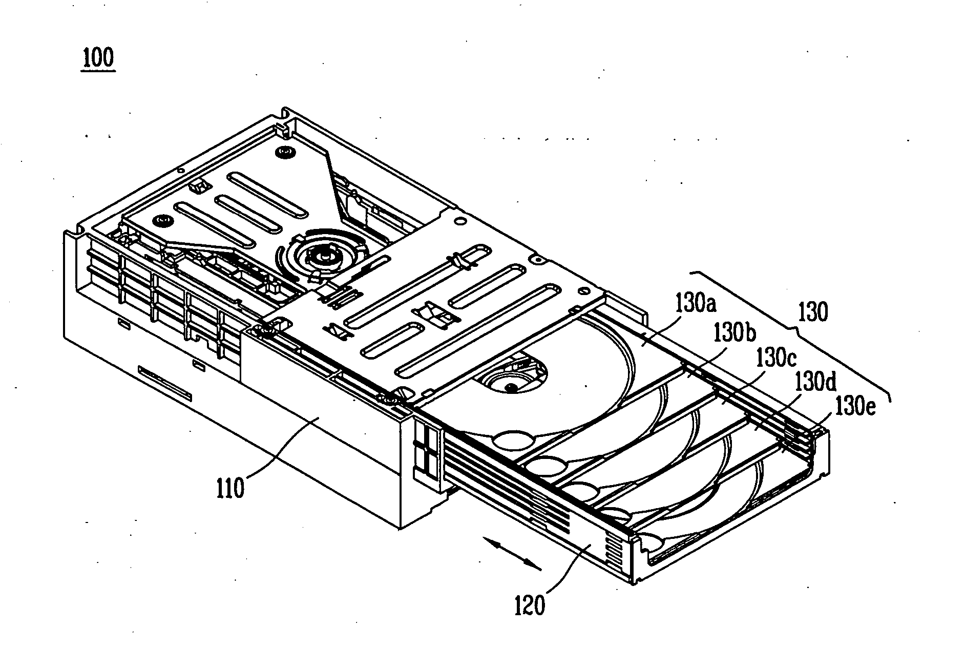
[0039] Referring to FIGS. 5 to 10, in a stack type optical disk changer 100, a cartridge 120 is installed to slide into or out of a main frame 110, and a plurality of trays 130a to 130e are sequentially slidably installed inside the cartridge 120.

[0040] An optical pick-up (not shown) is disposed at the rear portion of the main frame 110, and a tray loading unit 140 for loading one of the trays 130a to 130e selected by the user, for example, the tray 130c to the optical pick-up is disposed at one inside portion of the main frame 110.

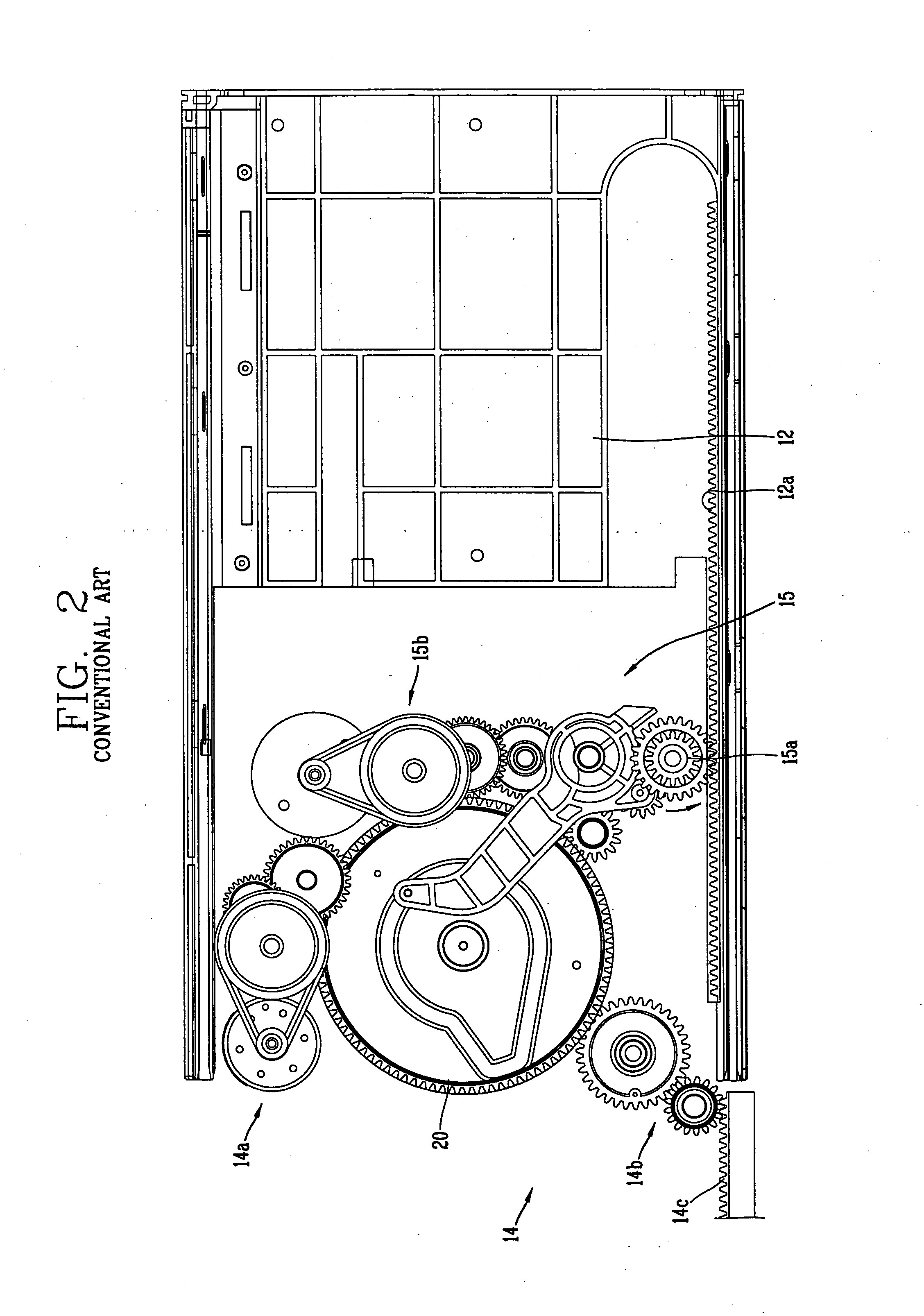
[0041] The tray loading unit 140 includes a plurality of tray loading gears 140b engaged with a cam 20 rotated by a driving unit 140a, for receiving power from the driving unit 140a, and a tray loading lever 140c for loading the tray 130c selected by the user to the optical pick-up by the tray...


PUM

PropertyMeasurementUnit
timeaaaaaaaaaa
movementaaaaaaaaaa
rotationaaaaaaaaaa

Abstract

The present invention discloses a stack type optical disk changer including a main frame, a cartridge slidably installed on the main frame, a plurality of disk trays slidably stacked in the cartridge, and a cartridge movement preventing means installed in the main frame, for selectively stopping movement of the cartridge. The stack type optical disk changer maintains quality of sound or image of an optical disk, and prevents damages of the optical disk, mis-operations and breakage, by preventing the optical disk from being separated from the tray.

Description

BACKGROUND OF THE INVENTION [0001] 1. Field of the Invention [0002] The present invention relates to a stack type optical disk changer, and more particularly to, a stack type optical disk changer which can prevent movement of a cartridge and each tray. [0003] 2. Description of the Background Art [0004] In general, an optical disk changer charges a plurality of optical disks into each tray, so that the user can freely select and reproduce a target optical disk. The optical disk changer is classified into a rotary type optical disk changer and a stack type optical disk changer. [0005] The stack type optical disk changer which can charge more optical disks than the rotary type optical disk changer has been recently popularly used. [0006]FIG. 1 is a perspective view illustrating a conventional stack type optical disk changer, FIG. 2 is a plane view illustrating an operation of taking a cartridge out of a main frame in the conventional stack type optical disk changer, FIG. 3 is a plane v...

Claims


Application Information

Patent Timeline
Patent Type & Authority Applications(United States)
IPC IPC(8): G11B17/22G11B17/30
CPCG11B17/22G11B17/30G11B17/225
Inventor KIM, SANG-JOEYU, DONG-KILL
Owner LG ELECTRONICS INC
Why Eureka
Try Eureka