

Height adjustable chair for a keyboard instrument
a keyboard instrument and adjustable chair technology, applied in the field of chairs with height adjustment ability, can solve the problems of troublesome and difficult, and conventional chairs are not handy in use, and achieve the effect of reducing the number of chairs
- Summary
- Abstract
- Description
- Claims
- Application Information
AI Technical Summary
Benefits of technology
Problems solved by technology
Method used
Image

Examples
Embodiment Construction
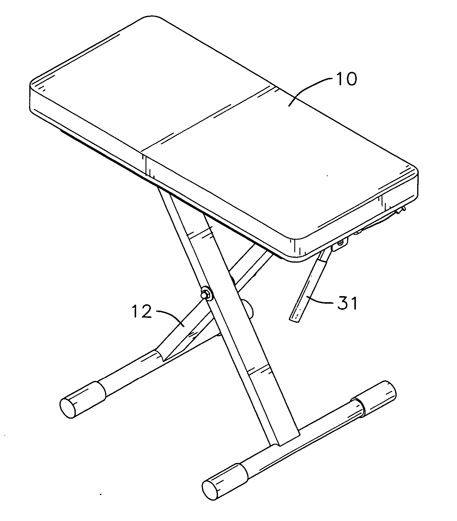
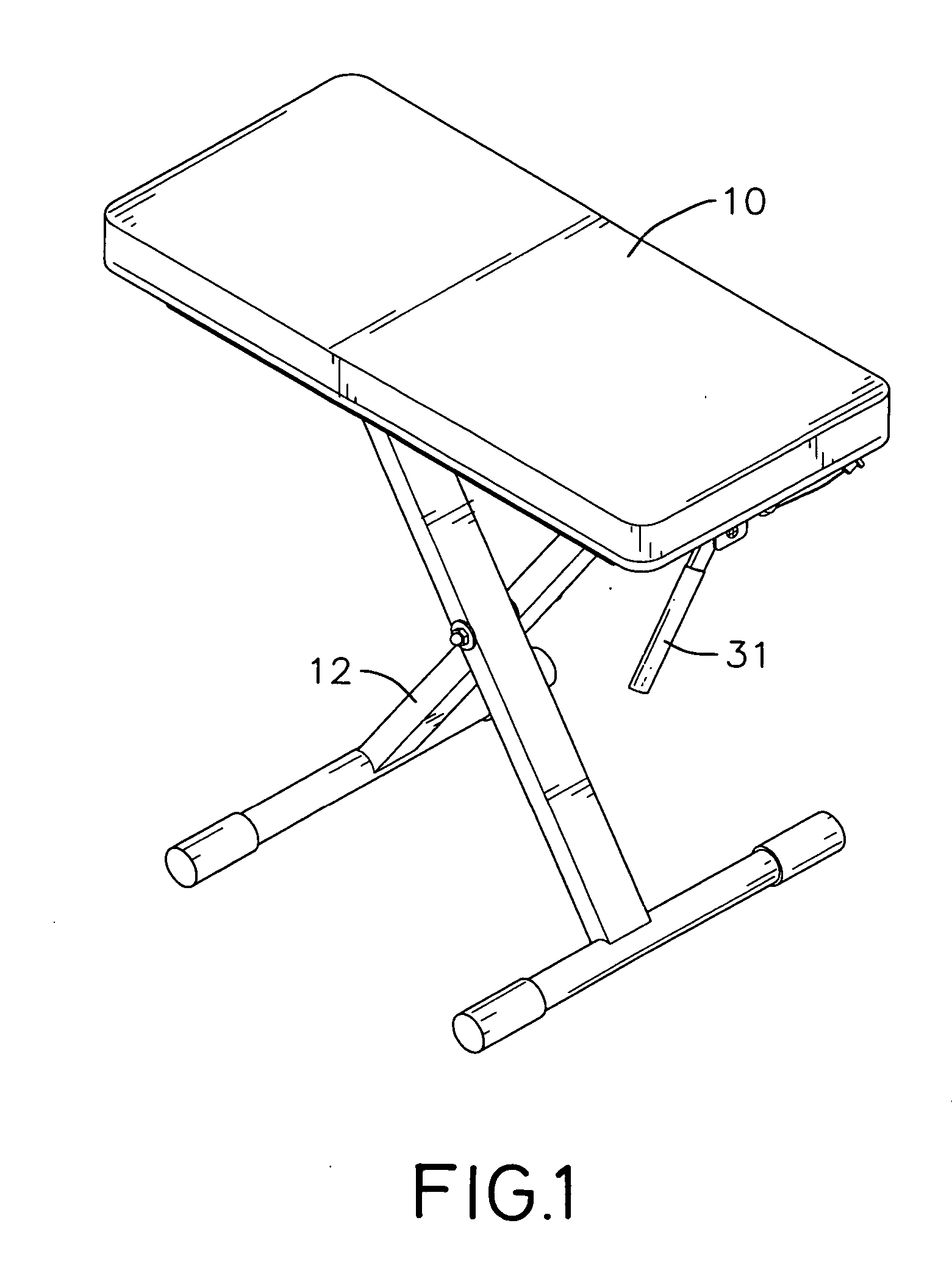
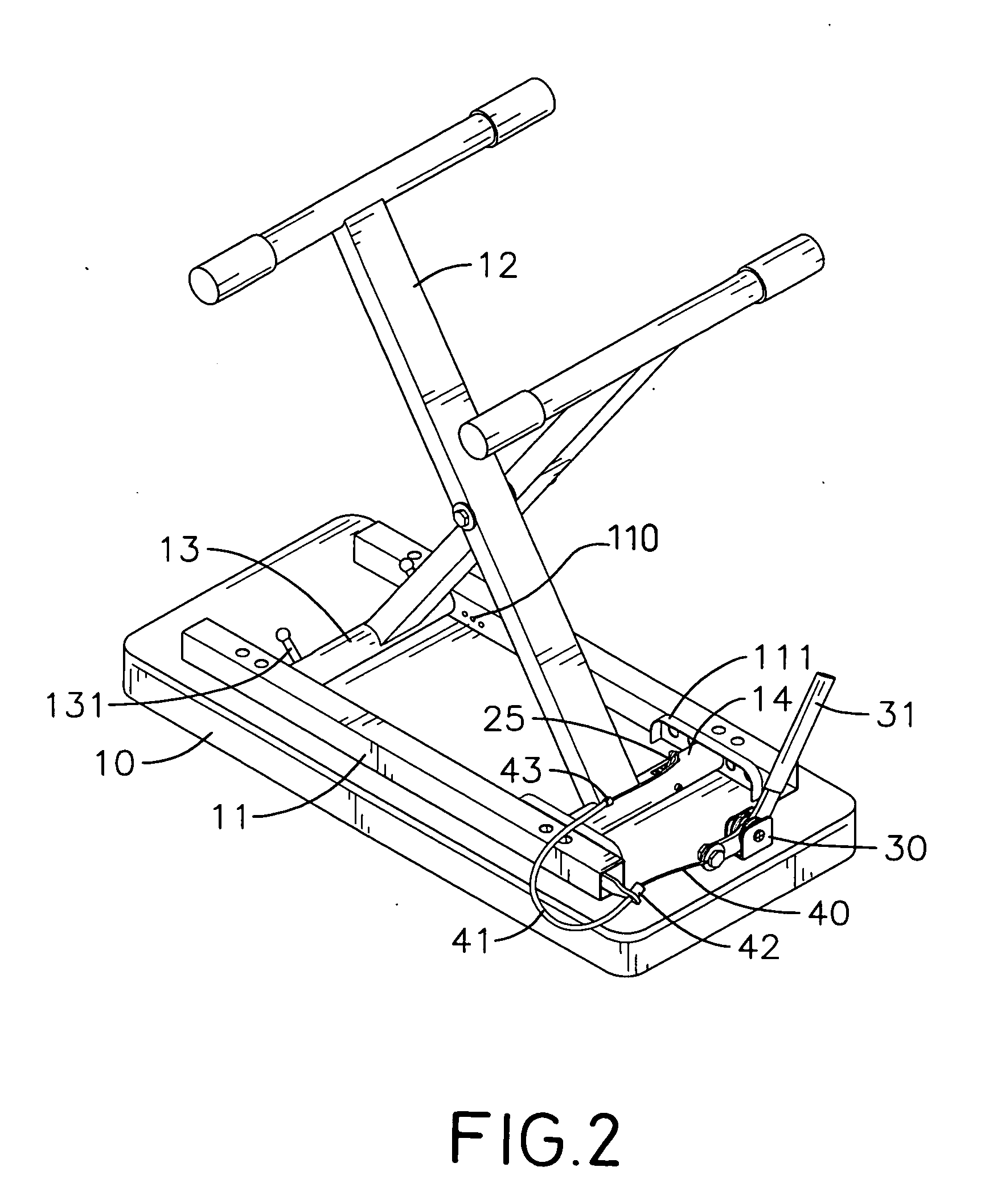
[0020] With reference to FIGS. 1 and 2, it is noted that the height adjustable chair in accordance with the present invention includes a seat (10) and two legs (12) pivotally interconnected with one another.
[0021] Two transverse bars (11) are horizontally and securely attached to a bottom face of the seat (10). A first cross bar (13) and a second cross bar (14) are sandwiched between the two transverse bars (11). An inner side face of each of the two transverse bars (11) is provided with multiple adjusting holes (110) to respectively receive therein a spring-driven positioning lever (131). That is, two spring-driven positioning levers (131) are respectively received inside two mutually aligned adjusting holes (110) respectively defined in the inner side faces of the two transverse bars (11) to position one of the legs (12). Because the structure and function of how the positioning lever (131) works is the same as that described in the description to FIG. 9, detailed description the...
PUM
 Abstract
Description
Claims
Application Information