Vertical take-off and landing aircraft

a vertical take-off and landing technology, applied in the direction of vertical landing/take-off aircraft, aircraft convertible vehicles, transportation and packaging, etc., can solve the problem of tend to hang down, and achieve the effect of easy and safe flying

Active Publication Date: 2005-10-20
TOYOTA JIDOSHA KK
View PDF11 Cites 59 Cited by
  • Summary
  • Abstract
  • Description
  • Claims
  • Application Information

AI Technical Summary

Benefits of technology

[0007] In view of the foregoing problems, this invention thus provides a small vertical take-off and landing aircraft that is both easy and safe to fly.
[0009] In a vertical take-off and landing aircraft having this kind of layout, the center of gravity lies low between the thrust generators at the front and rear of the aircraft, such that during flight it tends to hang down due to the thrust generated by the fore and aft thrust generators. As a result, the stability of the aircraft in flight is increased, which improves safety.
[0010] Further, arranging the thrust generators at the fore and aft of the aircraft enables the width of the aircraft to be reduced, while providing the occupant seat so that an occupant is seated in a sitting posture enables the height of the aircraft to be reduced. As a result, the aerodynamic moments which act on the aircraft due to air resistance and crosswinds and the like during flight are able to be suppressed, thereby improving both flight stability and fuel efficiency.

Problems solved by technology

In a vertical take-off and landing aircraft having this kind of layout, the center of gravity lies low between the thrust generators at the front and rear of the aircraft, such that during flight it tends to hang down due to the thrust generated by the fore and aft thrust generators.

Method used


Image

  • Vertical take-off and landing aircraft
  • Vertical take-off and landing aircraft
  • Vertical take-off and landing aircraft

Examples


Embodiment Construction

[0048] In the following description and the accompanying drawings, the present invention will be described in more detail with reference to exemplary embodiments.

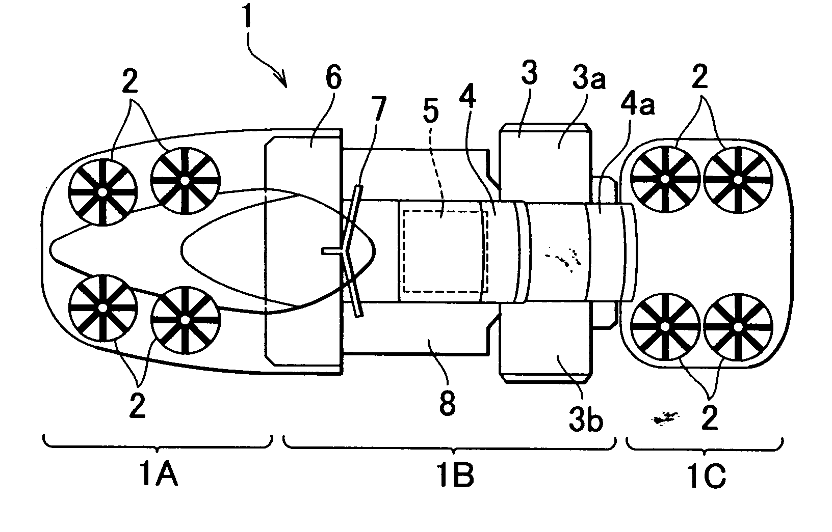
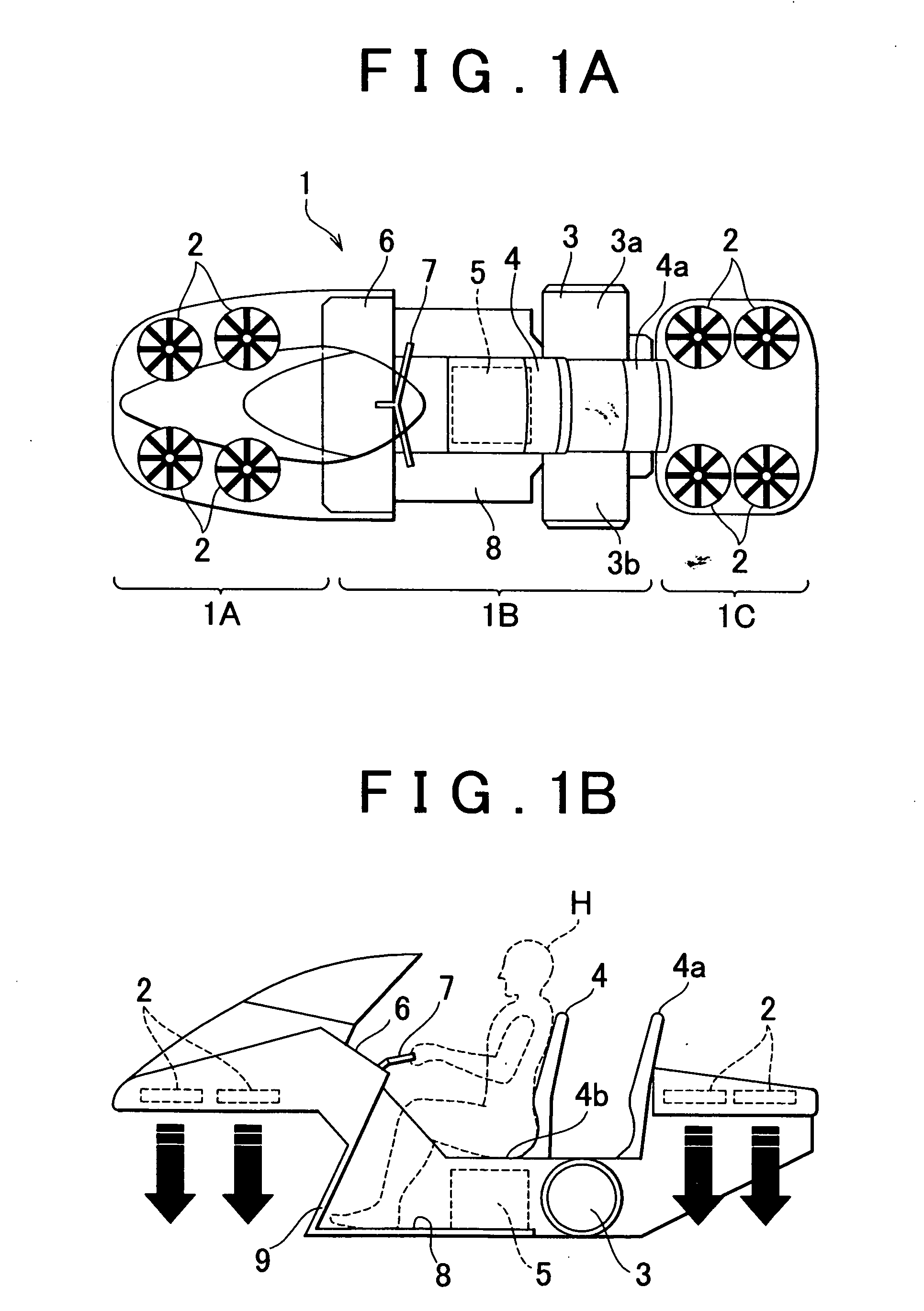
[0049] An outline of a vertical take-off and landing aircraft (hereinafter simply referred to as “aircraft”) according to a first exemplary embodiment of the invention is shown in FIGS. 1A and 1B, FIG. 1A being a top view and FIG. 1B being a side view. In this specification, directions such as front (fore), rear (aft), left, right, up, and down are to be understood as being with respect to the operator of the aircraft unless otherwise specified.

[0050] An aircraft 1 is made up of three sections, which are, in order from the front of the aircraft, an aircraft front section 1A, an aircraft mid section 1B, and an aircraft rear section 1C. Overall, the aircraft 1 is narrow in the width direction and long in the fore-aft direction.

[0051] Four fans 2, which function as thrust generators, are provided at the aircraft front secti...


PUM


Abstract

A vertical take-off and landing aircraft is provided with a plurality of thrust generators which generate thrust substantially vertically upward with respect to the aircraft; a first prime mover which drives the thrust generators, and an occupant seat. At least one of the thrust generators is disposed at either a front section of the aircraft or a rear section of the aircraft, and the remaining thrust generator or thrust generators are disposed at either the rear section or the front section, whichever the at least one of the thrust generators is not disposed at. The prime mover and a sitting surface of the occupant seat are disposed between the at least one of the thrust generators at the front section of the aircraft and the at least one of the thrust generators at the rear section of the aircraft, and in a position lower than all of the thrust generators. The center of gravity of the vertical take-off and landing aircraft is below the center of the aircraft and hangs down when the aircraft is in flight due to the thrust generated by the thrust generators.

Description

INCORPORATION BY REFERENCE [0001] The disclosure of Japanese Patent Application No. 2003-365112 filed on Oct. 24, 2003 including the specification, drawings and abstract is incorporated herein by reference in its entirety. BACKGROUND OF THE INVENTION [0002] 1. Field of the Invention [0003] The invention relates to a small vertical take-off and landing aircraft capable of being used in rescue operations and the like. [0004] 2. Description of the Related Art [0005] One known representative example of a vertical take-off and landing aircraft is a helicopter. Another such vertical take-off and landing aircraft disclosed in JP(A) 2002-370696 is provided with a plurality of propeller units for generating lift. These aircraft, however, lack maneuverability due to their large size. In addition, the propeller (i.e., the rotor) extends beyond the periphery of the body of the aircraft which makes it difficult for rescue workers to get close to the site of an accident or fire or the like, thus ...

Claims


Application Information

Patent Timeline
Patent Type & Authority Applications(United States)
IPC IPC(8): B64C29/00B60F5/02
CPCB64C29/0025B60F5/02
Inventor ISHIBA, MASATSUGU
Owner TOYOTA JIDOSHA KK
Why Eureka
Try Eureka