Al technical title is built by PatSnap Al team. It summarizes the technical point description of the patent document.
a fluorescent and rechargeable technology, applied in the field of fluorescent utility lights, can solve the problems of not being able to properly orient the light, prone to tube breakage, and difficult to find a place to hang the light,
Inactive Publication Date: 2006-06-29
ALERT SAFETY LITE PRODS
View PDF45 Cites 26 Cited by
Summary
Abstract
Description
Claims
Application Information
AI Technical Summary
This helps you quickly interpret patents by identifying the three key elements:
Problems solved by technology
Method used
Benefits of technology
[0008] The present invention concerns a utility light comprising: a light housing having an upper light portion and a lower handle portion, the upper light portion having a lens opening; a removable lens assembly closing the lens opening and having a receiver; and a locking means cooperating with the light housing and the lens assembly and including a locking tab being slidably movable between a locked position engaging the receiver and preventing removal of the lens assembly from the lens opening and an unlocked position permitting removal of the lens assembly from the lens opening.
Problems solved by technology
However, a number of problems have arisen, particularly in attempting to adapt a fluorescent tube to a satisfactory portable assembly, including electrical contact problems with the tubes, and problems arising when the tubes need replacement.
Portable light assemblies are also notoriously and disadvantageously susceptible to tube breakage, primarily because portable light assemblies are much more likely to be handled roughly, dropped or, at a minimum, subject to jarring, vibration, and the like.
Those skilled in the art will also realize that because of the frequently changing location of the utility light, finding a location for hanging and correctly orienting the light is often difficult.
Method used
Image
Click on the blue label to locate the original text in one second.
Reading with bidirectional positioning of images and text.
Examples
Embodiment Construction
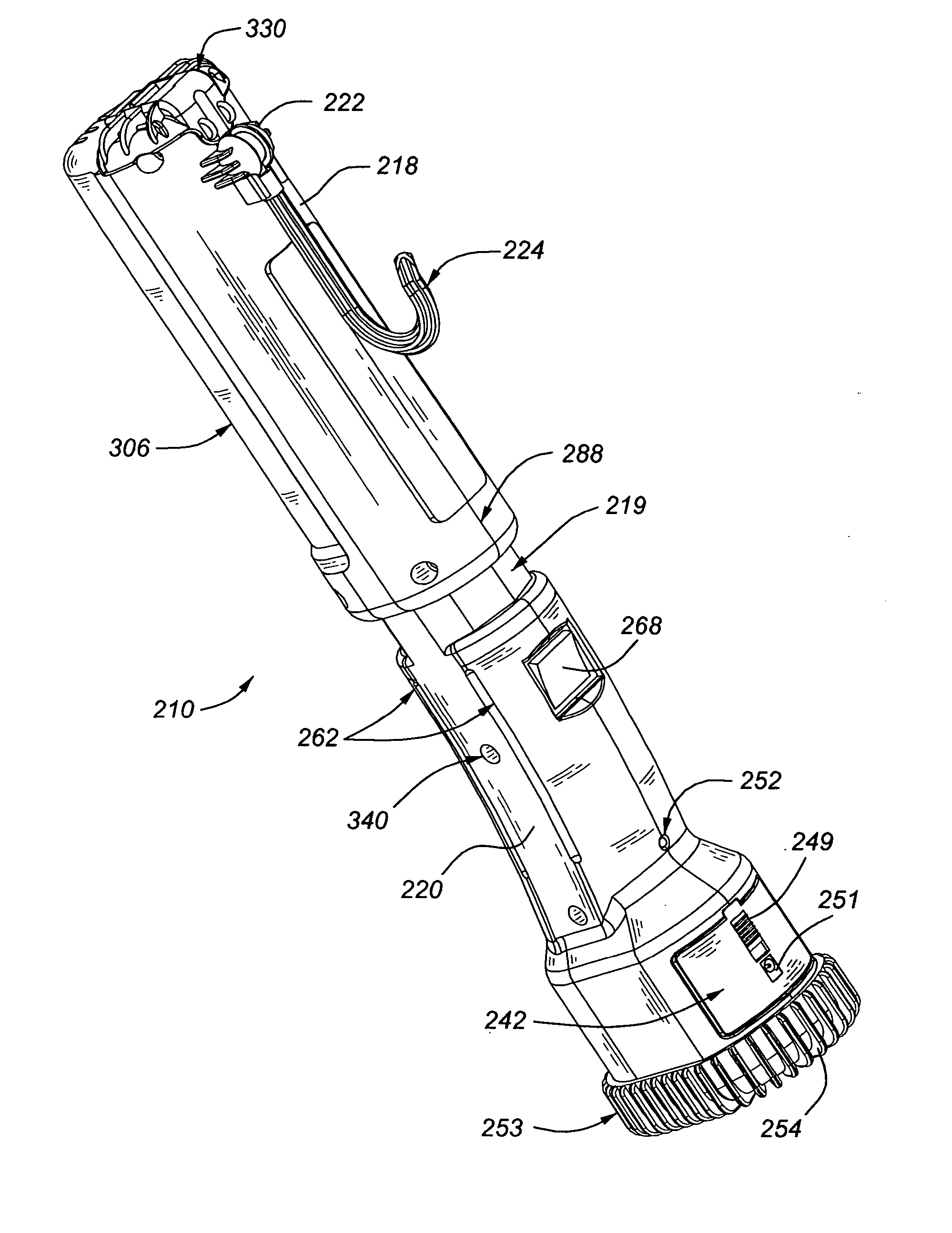
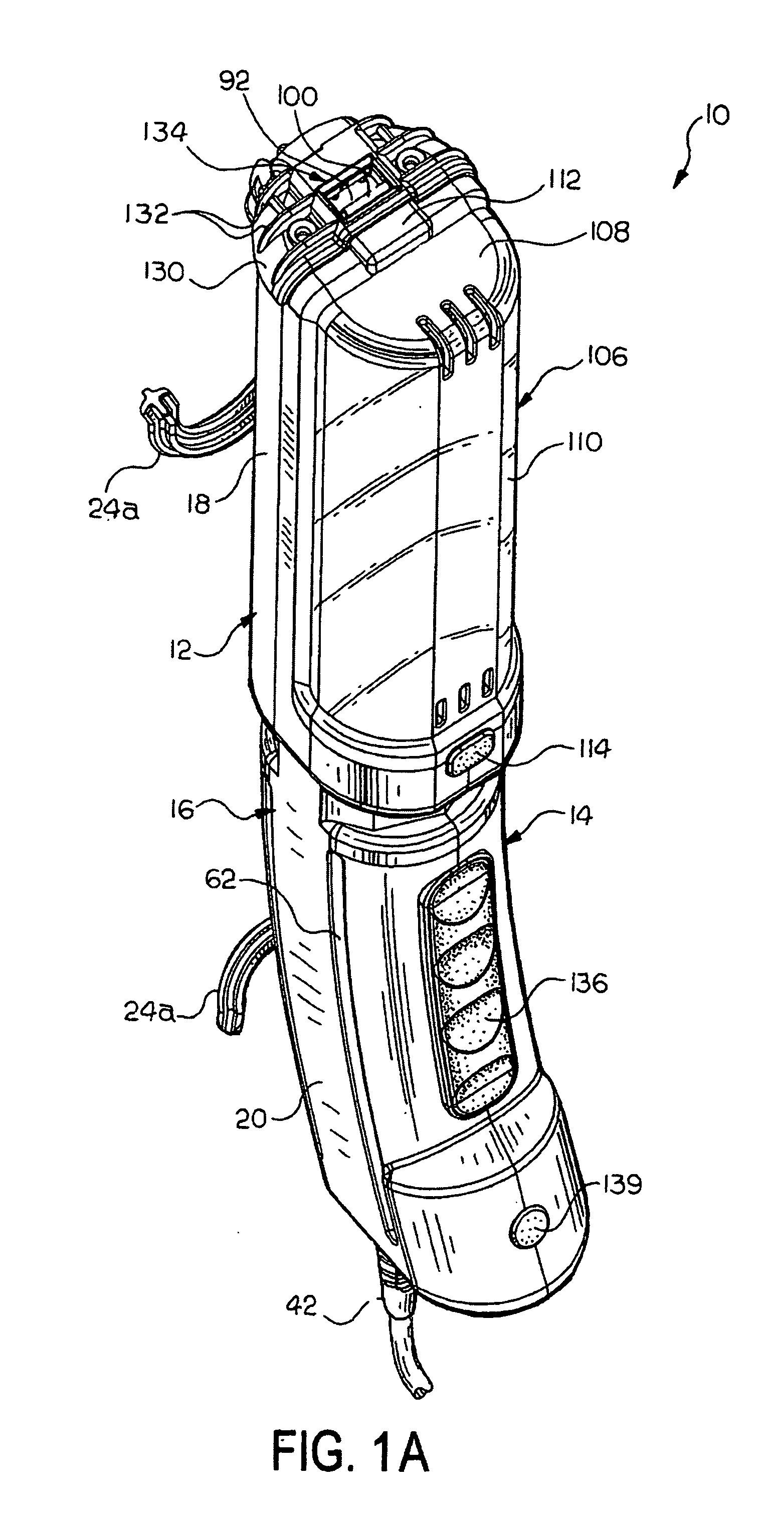
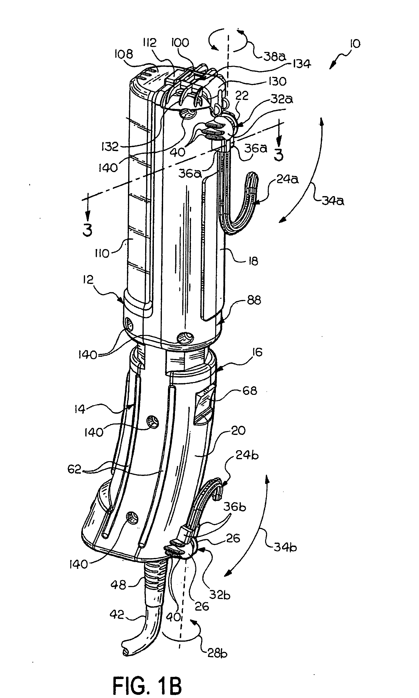
[0028] Referring now to FIGS. 1A, 1B and 2-5, a fluorescent utility light is indicated generally at 10. The utility light 10 includes a vertically split hollow light housing 12 formed in two housing halves 14 and 16 with an elongated upper light portion 18 extending from a hollow lower handle portion 20. The handle portion 20 is preferably ergonomically curved to allow the utility light 10 to be easily manipulated during use. The housing 12 is preferably formed of a lightweight material, such as plastic, as the utility light 10 is contemplated to be both handheld and portable.
[0029] Each half 14 and 16 of the split housing 12 includes an outwardly extending half upper socket 22 for receiving an upper hook 24a and an outwardly extending half lower socket 26 for receiving a lower hook 24b. The upper hook 24a and the lower hook 24b are substantially identical and include ball portions 28a and 28b respectively that are connected to shank portions 30a and 30b respectively. The ball port...
PUM
Abstract
A utility light has a dual fluorescent lamp assembly mounted in a housing with a removable lens for ease of lamp replacement. The lens is releasably retained at an upper end by a locking tab. The housing has a swivel hook, a handle cushion, a housing cushion at the upper end, and a bottom cushion at a lower end. The lamp assembly is powered by a battery pack assembly releasably mounted in a handle portion of the housing for removal and insertion into a charging stand.
Description
CROSS-REFERENCE TO RELATED APPLICATIONS [0001] This application is a continuation-in-part of the co-pending utility application Ser. No. 10 / 898,856 filed on Jul. 26, 2004, which is a continuation-in-part of the U.S. design patent application serial no. 29 / 206,355, filed on May 28, 2004, now U.S. Pat. No. D501,687, and U.S. design patent application serial no. 29 / 206,356, filed on May 28, 2004, now U.S. Pat. No. D501,688.BACKGROUND OF THE INVENTION [0002] The present invention relates generally to illumination devices and, in particular, to a fluorescent utility light. [0003] Portable lights, which can be manually moved and suspended about a work site to aid a user to obtain the best lighting conditions, are well known. It has been the practice to use incandescent light bulbs, suitably encased in light guards, for this purpose. Such lights are often referred to as trouble lamps, extension lights, work lights, inspection lights, utility lights, and the like, and are commonly employed ...
Claims
Application Information
Patent Timeline
Application Date:The date an application was filed.
Publication Date:The date a patent or application was officially published.
First Publication Date:The earliest publication date of a patent with the same application number.
Issue Date:Publication date of the patent grant document.
PCT Entry Date:The Entry date of PCT National Phase.
Estimated Expiry Date:The statutory expiry date of a patent right according to the Patent Law, and it is the longest term of protection that the patent right can achieve without the termination of the patent right due to other reasons(Term extension factor has been taken into account ).
Invalid Date:Actual expiry date is based on effective date or publication date of legal transaction data of invalid patent.
Patent Type & Authority Applications(United States)