Pedaling force sensor and pedaling force detection device using the sensor

a detection device and pedaling force technology, applied in the field of pedaling force sensor and pedaling force detection device using the sensor, can solve the problems of low structural reliability, impaired detecting function of the sensor, and difficult handling

Inactive Publication Date: 2006-07-27
PANASONIC CORP
View PDF13 Cites 19 Cited by
  • Summary
  • Abstract
  • Description
  • Claims
  • Application Information

AI Technical Summary

Benefits of technology

[0011] The present invention is directed to solve the problems pointed out above and provides a force-on-pedal sensor having a simple structure, high structural reliability and easy-handling.

Problems solved by technology

However, the conventional force-on-pedal sensor has a complicated structure because it is required an airtight characteristic to seal liquid 38, so that structural reliability is low.
In addition, if bellows 32 is injured in assembling, liquid 38 is leaked and a detecting function of the sensor is impaired, therefore handling is not easy.

Method used


Image

  • Pedaling force sensor and pedaling force detection device using the sensor
  • Pedaling force sensor and pedaling force detection device using the sensor
  • Pedaling force sensor and pedaling force detection device using the sensor

Examples


Embodiment Construction

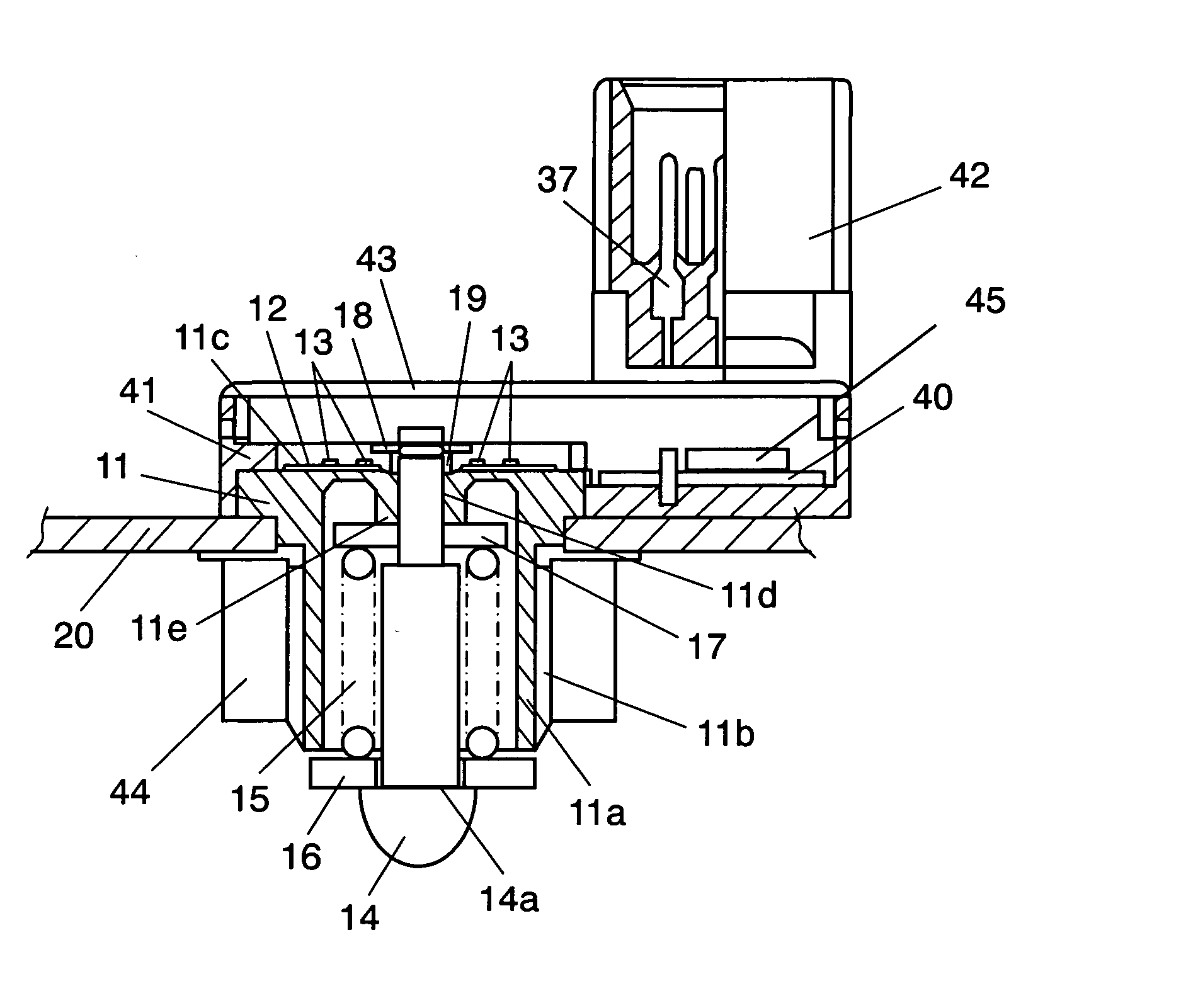
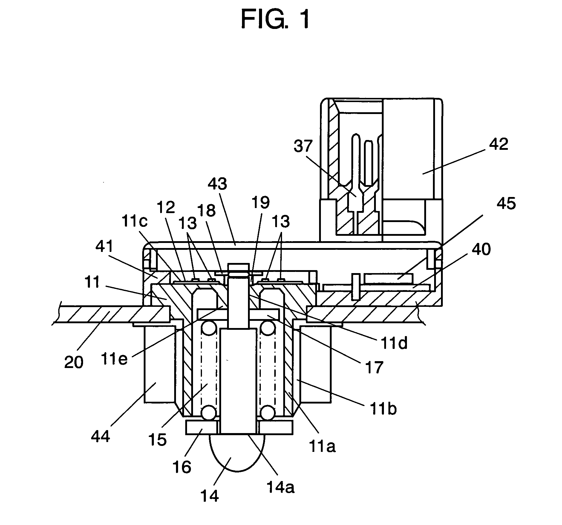
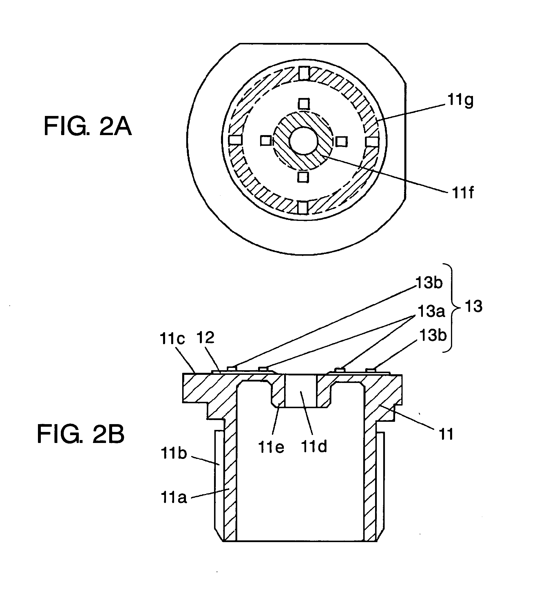
[0069] A sensor of the present invention includes the following structures:

[0070] a cylindrical substrate whose one end is closed having: [0071] a hole at a center of its side section; and [0072] a strain resistance element via an insulating layer at its side section;

[0073] a coil spring coaxially inserted from an open end of the substrate;

[0074] an inputting shaft having a stepped part contacted with one end of the coil spring and inserted in the hole in such a manner that a part of the inputting shaft is protruded from the hole; and

[0075] a stopper at a position where the inputting shaft is protruded.

[0076] Using the structure mentioned above, the stout sensor having high structural reliability can be provided. In addition, by providing a screw section at an outer circumference of a cylindrical section of the substrate, mounting becomes easy and assembling performance improves.

[0077] Further, according to the sensor of the present invention, a first stopper having an outer d...


PUM

PropertyMeasurementUnit
forceaaaaaaaaaa
strain resistanceaaaaaaaaaa
outer circumferenceaaaaaaaaaa

Abstract

A force-on-pedal sensor of the present invention includes a cylindrical substrate (11) whose one end is closed having: a hole part (11d) at a center of its side section (11c); and a strain resistance element (13) via an insulating layer (12) at its side section (11c), a coil spring (15) coaxially inserted from an open end of the substrate (11), an inputting shaft having a stepped part (14a) contacted with one end of the coil spring (15) and inserted in the hole part (11d) in such a manner that a part of the inputting shaft (14) is protruded from the hole part (11d), and a stopper at a position where the inputting shaft (14) is protruded.

Description

TECHNICAL FIELD [0001] The present invention relates to a force-on-pedal sensor for detecting force-on-pedal exerted on an accelerator, a brake or the like of a motor vehicle, for example, and a pedal-pressure detecting device using the same. BACKGROUND ART [0002]FIGS. 4, 5A and 5B are a detailed sectional view and general views of a conventional force-on-pedal sensor and pedal-pressure detecting device using the same. [0003] As shown in FIG. 4, spring 23 is positioned between first cover member 21 and second cover member 22 both of which have a U-like glass shape in section, and they are disposed on sensor head 31. [0004] Bellows 32 is formed beneath sensor head 31, and filled with liquid 38. Sensor chip 35 is positioned so as to be immersed in liquid 38, and electrically coupled with terminal 37 via bonding wire 36. [0005] As shown in FIGS. 5A and 5B, pedal section 4 is formed at one end of lever section 5, and force-on-pedal sensor 1 is formed at the other end thereof. Lever sect...

Claims


Application Information

Patent Timeline
Patent Type & Authority Applications(United States)
IPC IPC(8): G01L5/28B60T7/02B60T7/04B60T8/32G01L1/22G01L5/22G05G1/30G05G1/42
CPCB60T7/042B60T8/3255G01L1/2225G01L5/225G05G1/30G05G1/42
Inventor SAITO, KIYOSHIUEDA, SHINJIRO
Owner PANASONIC CORP
Why Eureka
Try Eureka