

Display board assembly
a technology for display boards and assembly parts, applied in writing boards, instruments, sport apparatus, etc., can solve the problems of markers or erasers being misplaced or not readily accessible to users of display boards
- Summary
- Abstract
- Description
- Claims
- Application Information
AI Technical Summary
Problems solved by technology
Method used
Image

Examples
Embodiment Construction
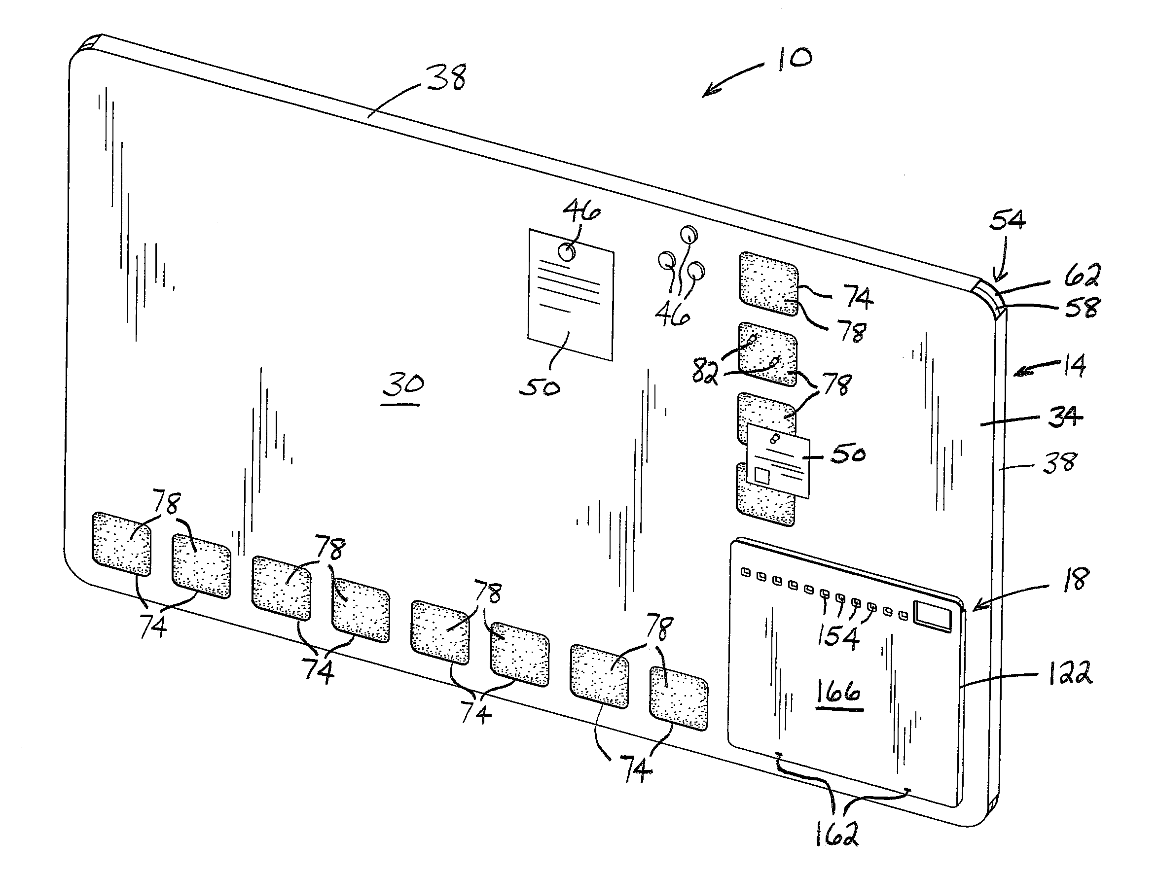
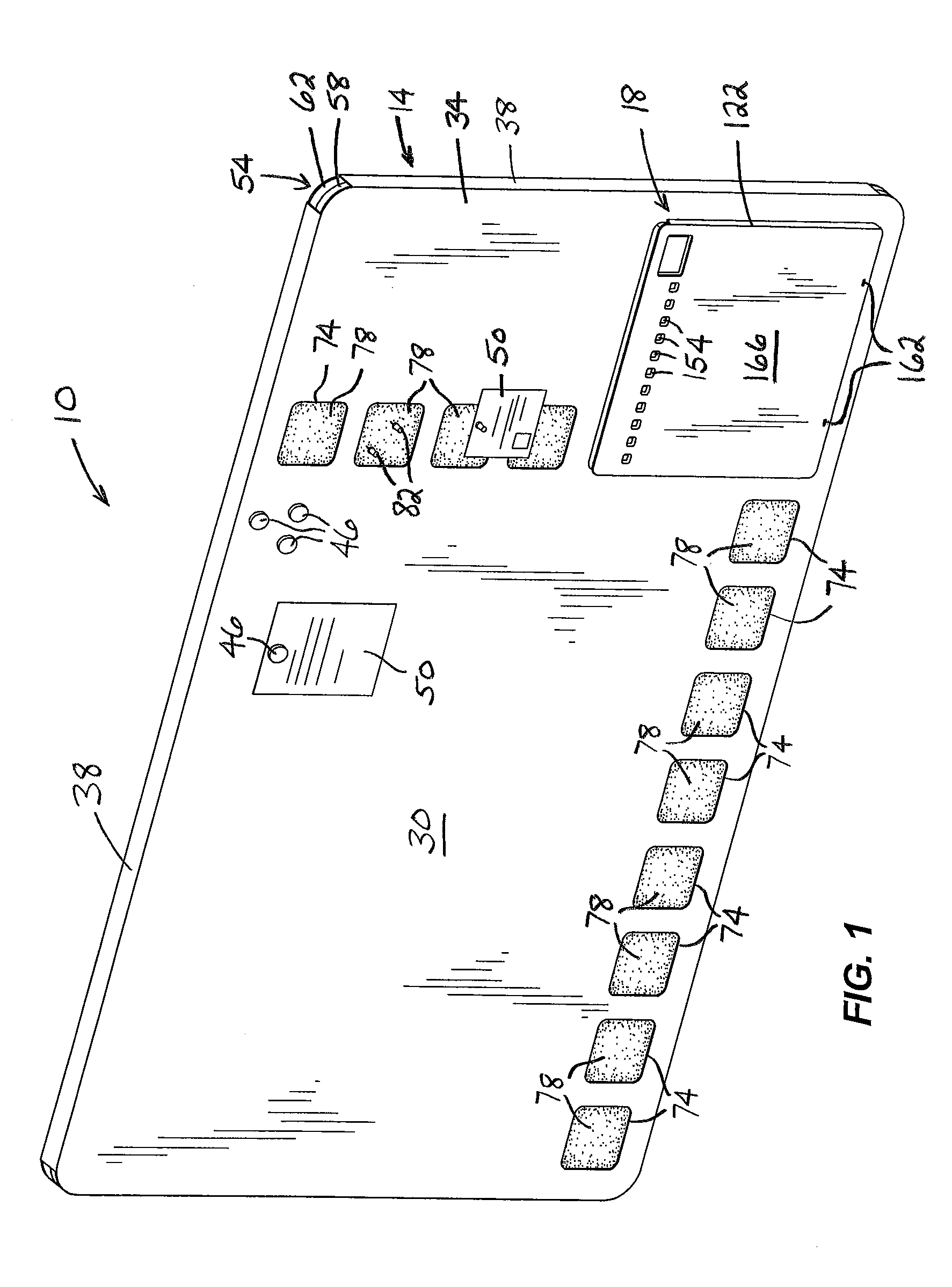
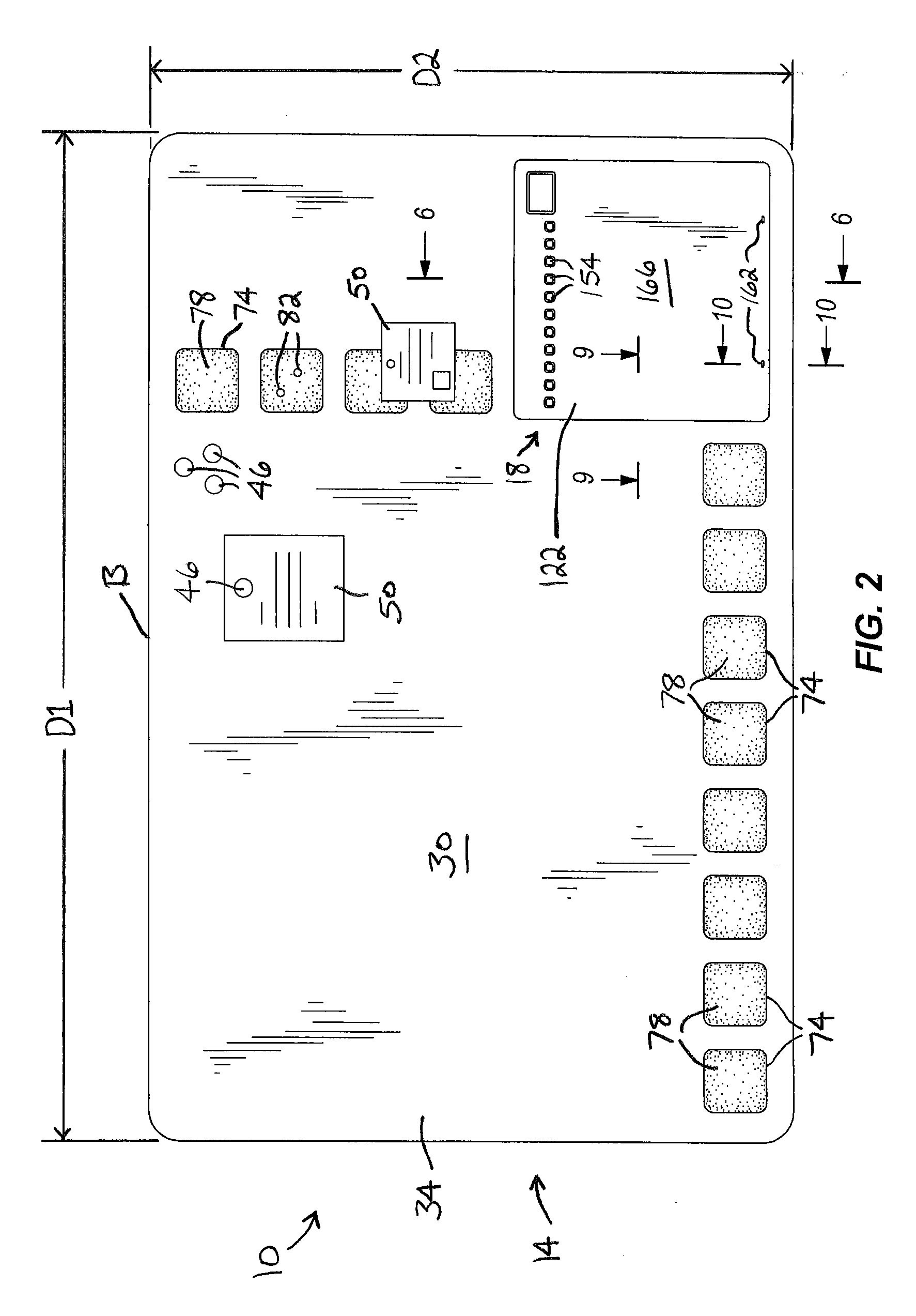
[0021]FIGS. 1 and 2 illustrate a display board assembly 10 including a display board 14 and a support member or caddy 18, configured to support items such as dry-erase markers 22 and an eraser 26, removably coupled to the display board 14 (see also FIG. 3). The illustrated display board 14 is rectangular-shaped, and therefore defines a major dimension D1 and a minor dimension D2. However, alternative constructions of the display board 14 may have any of a number of different shapes (e.g., circular, oval, square, and so forth). As shown in FIGS. 1 and 2, the display board 14 is oriented such that its major dimension D1 is substantially horizontal with respect to the ground, such that users of the display board 14 may write along the major dimension D1 of the display board 14. Alternatively, the display board 14 may be oriented such that its major dimension D1 is substantially vertical with respect to the ground, such that users of the display board 14 may write along the minor dimens...
PUM
| Property | Measurement | Unit |
|---|---|---|
| magnetic | aaaaa | aaaaa |
| magnetically attractive | aaaaa | aaaaa |
| physical or mechanical | aaaaa | aaaaa |
Abstract
Description
Claims
Application Information