Transmitting Apparatus and Receiving Apparatus

a technology which is applied in the field of transmitting apparatus and receiving apparatus, can solve the problems of no means to protect against illegal reception of data transmitted by the transmitting apparatus, and video bitstream or the like can be easily stolen by an illegal receiving apparatus, so as to achieve the effect of reducing confusion in the system establishmen

Inactive Publication Date: 2007-11-01
PANASONIC CORP
View PDF14 Cites 48 Cited by
  • Summary
  • Abstract
  • Description
  • Claims
  • Application Information

AI Technical Summary

Benefits of technology

[0033] In addition to the above advantages, the transmitting apparatus according to the present invention has an advantage that it can show an invalid tool.
[0034] Since the transmitting apparatus according to the present invention can show granulating information, confusion in system establishment can be advantageously reduced.
[0035] The receiving apparatus according to the present invention can update a tool by, for example, downloading, and can advantageously keep the latest protecting method.
[0036] In addition to the above advantages, the receiving apparatus according to the present invention can obtain entire tool information based on the tool list information.
[0037] In addition to the above advantages, the receiving apparatus according to the present invention can protect an invalid tool from being incorporated in the receiving apparatus.
[0038] In addition to the above advantages, the receiving apparatus according to the present invention obtains granulating information of a tool to make it possible to establish an optimum system.

Problems solved by technology

According to the conventional technique, a method of encrypting and protecting a video bitstream or the like is not performed, and the video bitstream or the like can be easily stolen by an illegal receiving apparatus.
More specifically, there are no means to protect against illegal reception of data transmitted by a transmitting apparatus.

Method used


Image

  • Transmitting Apparatus and Receiving Apparatus
  • Transmitting Apparatus and Receiving Apparatus
  • Transmitting Apparatus and Receiving Apparatus

Examples


first embodiment

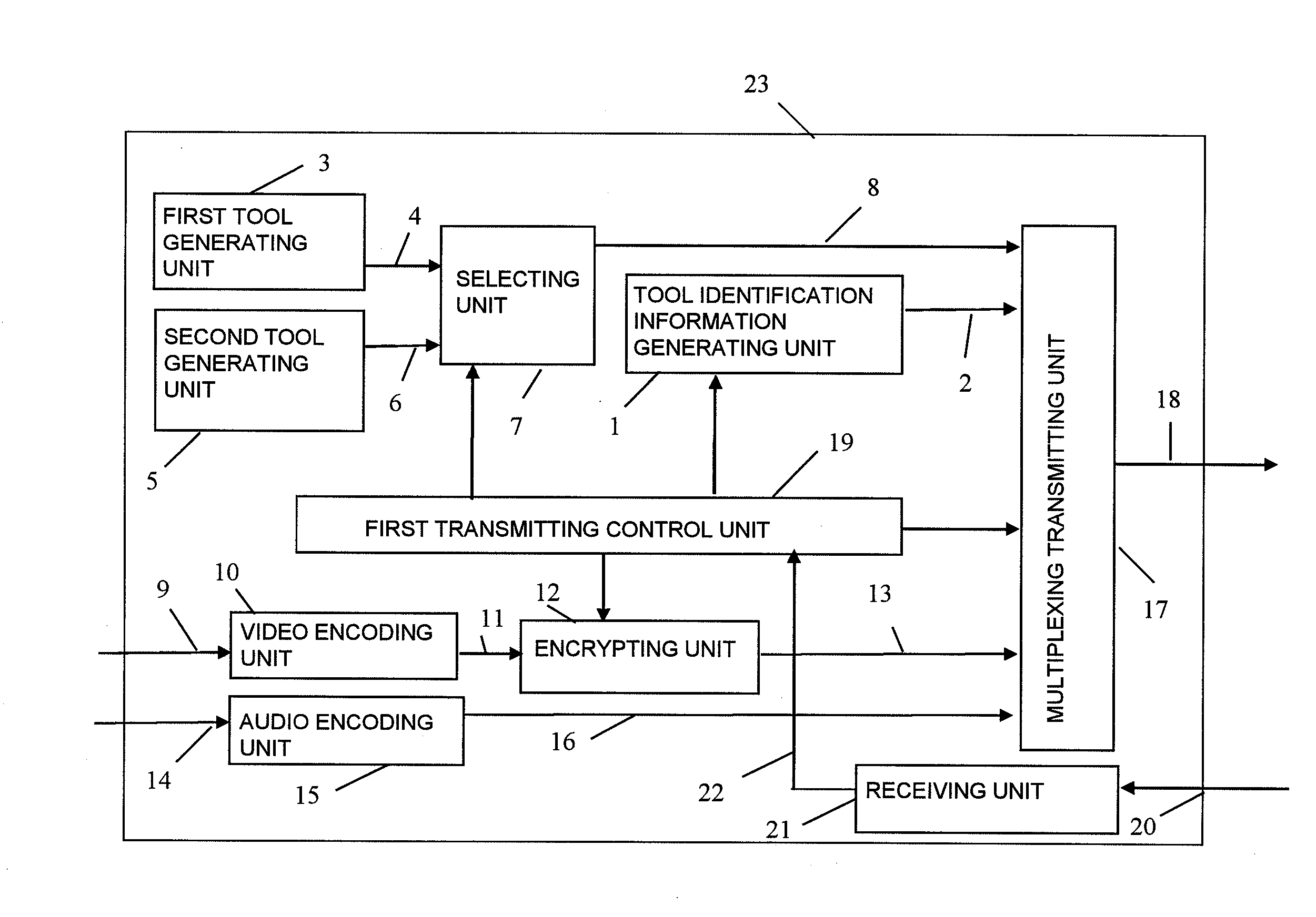
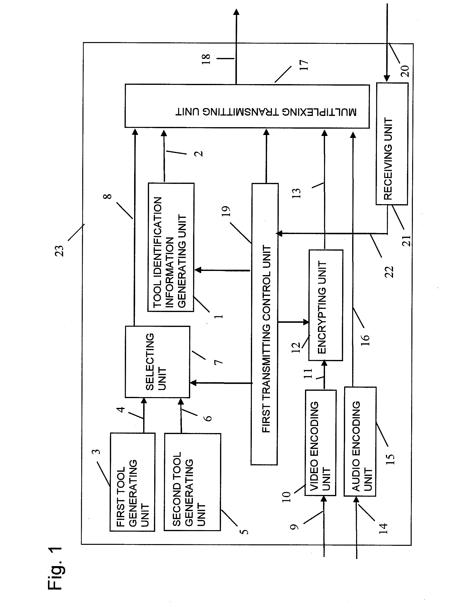
[0050]FIG. 1 is a block diagram showing a configuration of a transmitting apparatus according to a first embodiment of the present invention. In FIG. 1, the transmitting apparatus 23 includes a tool identification information generating unit 1 which generates tool identification information 2, a first tool generating unit 3 which generates a first tool 4, a second tool generating unit 5 which generates a second tool 6, a selecting unit 7 which switches and outputs the first tool 4 and the second tool 6, an encrypting unit 12, a multiplexing transmitting unit 17, a first transmitting control unit 19, a receiving unit 21, a video encoding unit 10 conforming to MPEG-2 video (ISO / IEC13818-2), and an audio encoding unit 15 conforming to MPEG-2 audio (ISO / IEC13818-3).

[0051] In FIG. 1, an input digital video signal 9 is compressed and encoded by the video encoding unit 10 into a video bitstream 11 conforming to MPEG-2, encrypted by the encrypting unit 12, and outputted as an encrypted vid...

second embodiment

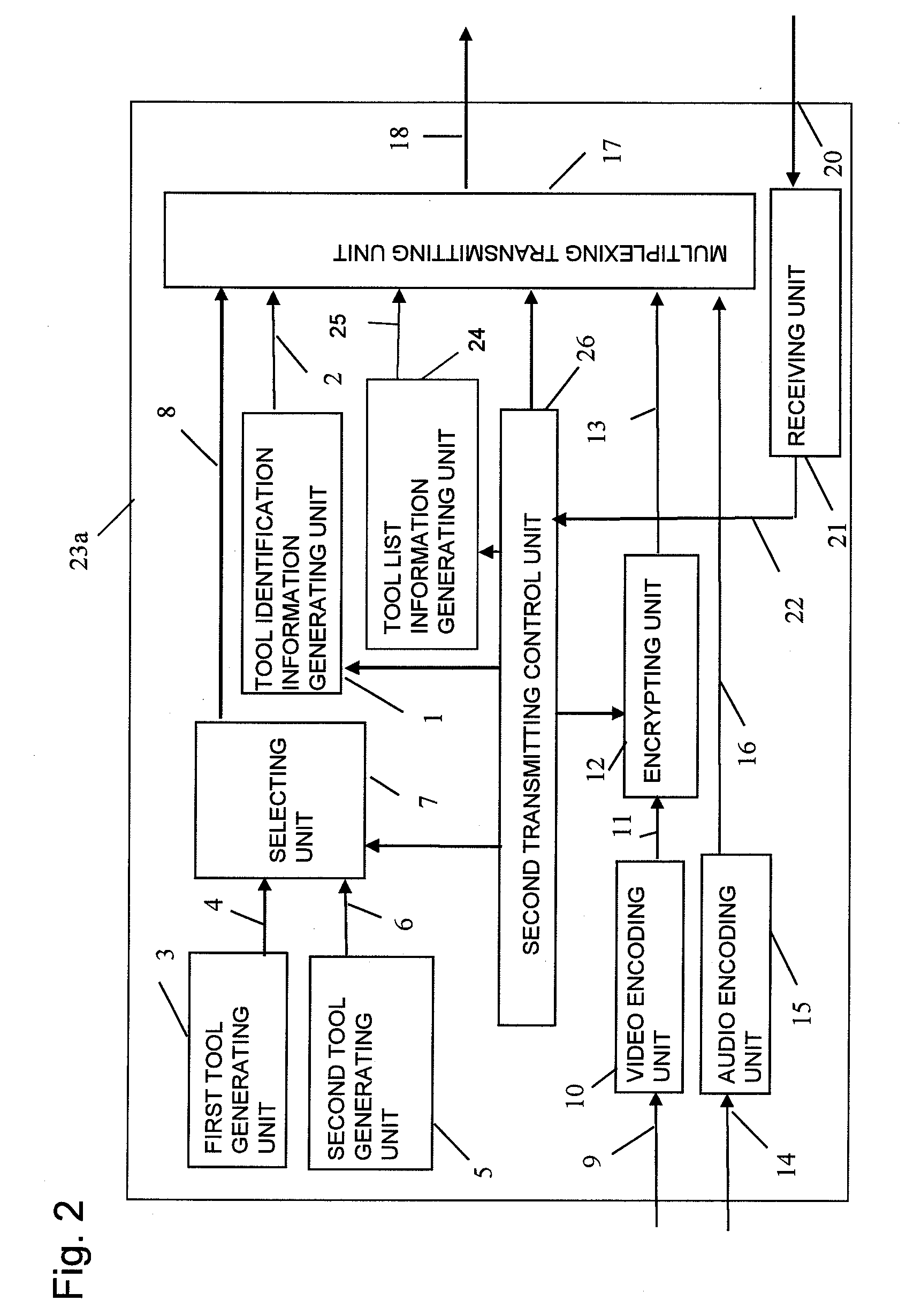
[0062] A second embodiment is similar to the first embodiment. The second and first embodiments are different in that information related to a tool is transmitted to a receiving apparatus as tool list information. FIG. 2 is a block diagram showing a configuration of a transmitting apparatus 23a according to the second embodiment. In FIG. 2, the transmitting apparatus 23a is different from the transmitting apparatus according to the first embodiment in that the transmitting apparatus 23a includes a transmitting control unit 26 in place of the first transmitting control unit and further includes a tool list information generating unit 24 which generates tool list information.

[0063] The second transmitting control unit 26 instructs the tool list information generating unit 24 to form a table listing the contents of Table 1 and generate a table as tool list information 25. In this manner, a receiving apparatus can see all tools with reference to the tool list information 25.

[0064] Oth...

third embodiment

[0066] A third embodiment is a transmitting apparatus similar to that of the second embodiment. The third embodiment is different from the second embodiment in that invalid tool information is described in the tool list information. FIG. 3 is a block diagram showing a configuration of a transmitting apparatus 23b according to the third embodiment. When compared with the transmitting apparatus according to the second embodiment, the transmitting apparatus 23b includes a third transmitting control unit 29 in place of the second transmitting control unit and further includes an invalid tool information generating unit 27.

[0067] In FIG. 3, a receiving unit 21 receives input information 20 and supplies received information 22 including information that a second tool causes a bug or a failure in reliability to the third transmitting control unit 29. The third transmitting control unit 29 instructs the invalid tool information generating unit 27 to generate invalid tool information 28 whi...


PUM


Abstract

A transmitting apparatus includes an encrypting unit operable to encrypt at least one of digital audio information and digital video information to generate encrypted digital AV information, a tool generating unit operable to generate a tool required to decode the encrypted digital AV information, a tool identification information generating unit operable to generate tool identification information for identifying the tool, a selecting unit operable to select a predetermined tool from a plurality of tools, a transmitting control unit operable to output an instruction for generating the tool identification information to the tool identification information generating unit and outputting an instruction for selecting the predetermined tool to the selecting unit, and a transmitting unit operable to transmit the encrypted digital AV information, the tool identification information, and the tool.

Description

BACKGROUND OF THE INVENTION [0001] 1. Field of the Invention [0002] The present invention relates to a transmitting apparatus which can safely transmit a signal including digitalized video information and digitalized audio information and a receiving apparatus which can receive the signal. [0003] 2. Description of the Related Art [0004]FIG. 9 shows a conventional example. FIG. 9 is a block diagram showing a conventional transmitting apparatus 502 and a conventional receiving apparatus 503. In FIG. 9, the transmitting apparatus 502 includes a video encoding unit 10 conforming to MPEG-2 video (ISO / IEC13818-2) and an audio encoding unit 15 conforming to MPEG-2 audio (ISO / IEC13818-3). The receiving apparatus 503 includes a video decoding unit 106 and an audio decoding unit 111. [0005] In FIG. 9, in the conventional transmitting apparatus 502, an input digital video signal 9 is outputted by the video encoding unit 10 as a video bitstream 11 compressed and encoded in conformity to MPEG-2 ...

Claims


Application Information

Patent Timeline
Patent Type & Authority Applications(United States)
IPC IPC(8): H04L9/00H04N7/167
CPCH04K1/00H04N7/1675H04N21/835H04N21/4405H04N21/2347H04L63/08H04L63/0428H04L63/06
Inventor UENO, TAKAFUMI
Owner PANASONIC CORP
Why Eureka
Try Eureka