Electrical power distribution system and method thereof

a technology of electric power distribution system and power distribution system, applied in emergency power supply arrangements, transportation and packaging, sustainable buildings, etc., can solve the problems of power quality and reliability problems, complete power failure, and uninterruptible power supply

Inactive Publication Date: 2008-01-24
WEG ELECTRIC CORP
View PDF5 Cites 37 Cited by
  • Summary
  • Abstract
  • Description
  • Claims
  • Application Information

AI Technical Summary

Problems solved by technology

Due to the long distances involved in the transmission of power, as well as unexpected increases in demands placed on the utility, end users often face power quality and reliability issues.
These power quality issues range from conditions such as undervoltage (sags), voltage spikes, surges, overvoltage, and noise to complete power failure.
When power quality and reliability are of great importance to the end user, they often rely on uninterruptible power supplies (UPS) to provide continuous power to meet the user's needs.
In facility's which utilize multiple metered electric utility services from the utility grid, this complexity is multiplied since traditionally, each utility feed required its own dedicated UPS or CHP system.
Since generation equipment is available in only discrete size ranges, the combining of devices often requires over sizing of equipment for any individual utility feed in the multi-utility service facility.
The use of discrete UPS and CHP systems also results in substantial wiring between the components, increasing the potential for incompatibilities and non-ideal system performance.

Method used


Image

  • Electrical power distribution system and method thereof
  • Electrical power distribution system and method thereof
  • Electrical power distribution system and method thereof

Examples


Embodiment Construction

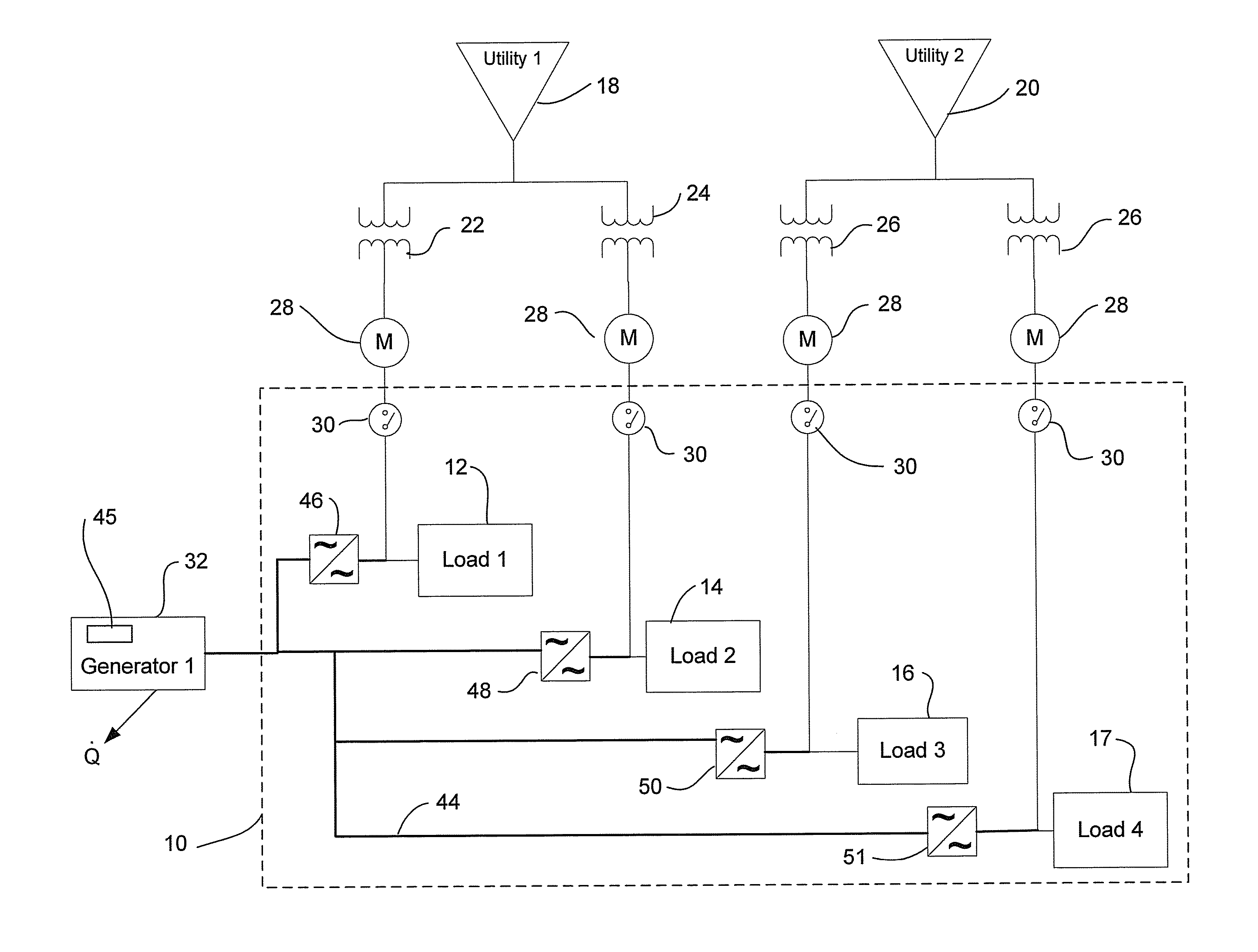
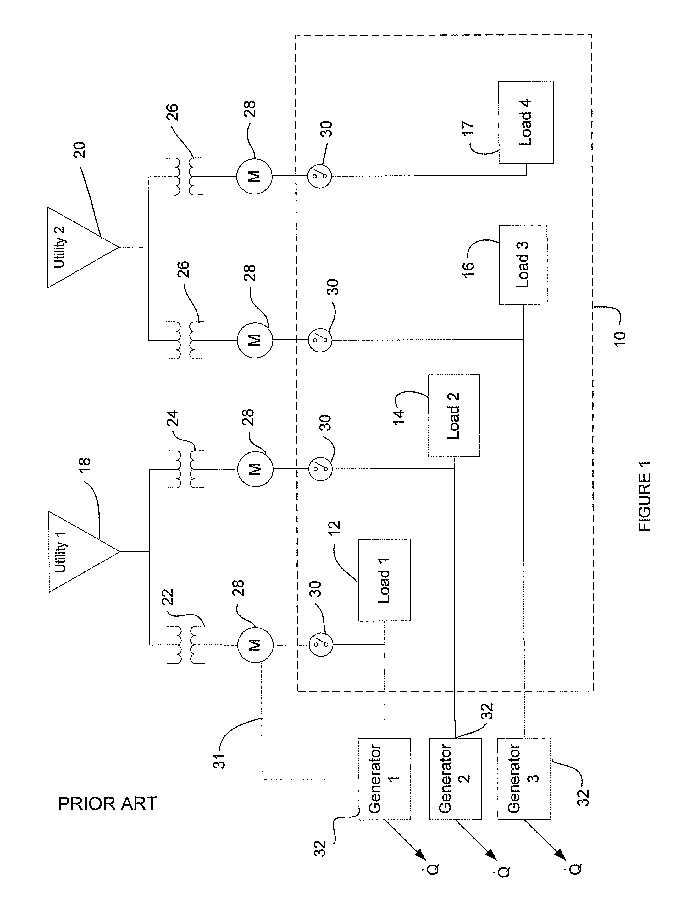
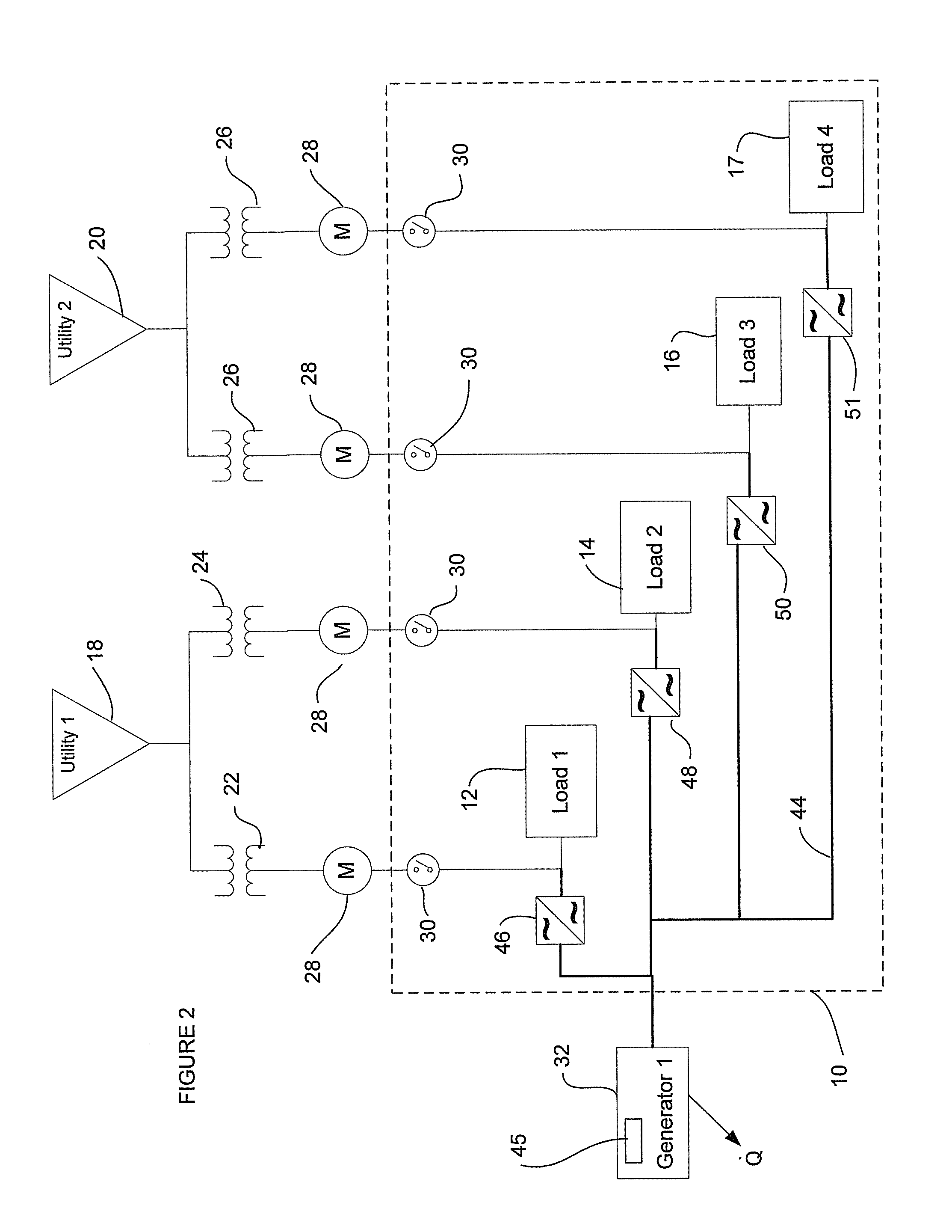
[0019] Traditionally, electrical power distribution and service was provided by a single utility which would provide all services required by a user, from the generation of the electricity, to the maintaining of the electrical grid. As the electrical power industry was deregulated, complexities often arose as consumers were allowed to purchase electricity from multiple suppliers while at the same time, their power needs were increasing. As a result, in large facilities, it has become common for multiple electrical service entrances to be connected to the facility. Occasionally the facility will also be fed electricity from different utility suppliers as well. As used herein, a facility means a single building, or a series of buildings such as a farm or office park, which are geographically located in close proximity to each other, typically being located less than five miles apart and preferably less than one mile apart.

[0020] A typical facility having multiple utility service entr...


PUM


Abstract

A system for providing auxiliary electrical power is provided. The system includes a plurality of loads and a plurality of power sources, each providing electrical power to one or more of the plurality of loads. At least one generator is electrically connected to the plurality of loads. Also, a plurality of power converters, each of the plurality of power converters being electrically connected between the at least one generator and one of the plurality of loads. An arrangement is also provided for increasing the reliability of power to a load through a connection with a parallel utility network.

Description

CROSS REFERENCE TO RELATED APPLICATIONS [0001] This application is a continuation of U.S. patent application Ser. No. 10 / 950,943 filed on Sep. 27, 2004 which is incorporated by reference in its entirety.FIELD OF INVENTION [0002] This disclosure relates generally to a system for providing a combined heat and power functionality to a facility and especially to a system for a facility having multiple utility services and a common electrical generation system in parallel with the utility services. BACKGROUND OF THE INVENTION [0003] A facility which uses a combined heat and power system (hereinafter referred to as “CHP”), or cogeneration, uses a single process to simultaneously produce both thermal energy and electrical power from a single fuel source. A typical CHP system utilizes one or more prime movers, such as a diesel engine, to drive an electrical generator. Heat which results from the generation of electricity is reclaimed and then used for other purposes such as community heatin...

Claims


Application Information

Patent Timeline
Patent Type & Authority Applications(United States)
IPC IPC(8): H02J3/38
CPCH02J3/005Y02B10/72H02J9/08Y02B10/70H02J3/007
Inventor MCNAMARA, JAMES L.SKROSKI, E. MICHAELTIERSON, JANPETTER, JEFFREY
Owner WEG ELECTRIC CORP
Why Eureka
Try Eureka