

Multi-Battery Charger
- Summary
- Abstract
- Description
- Claims
- Application Information
AI Technical Summary
Benefits of technology
Problems solved by technology
Method used
Image

Examples
Embodiment Construction
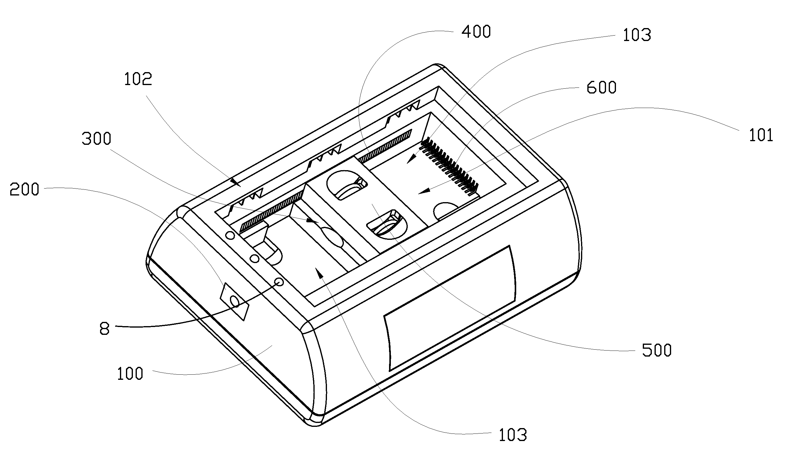
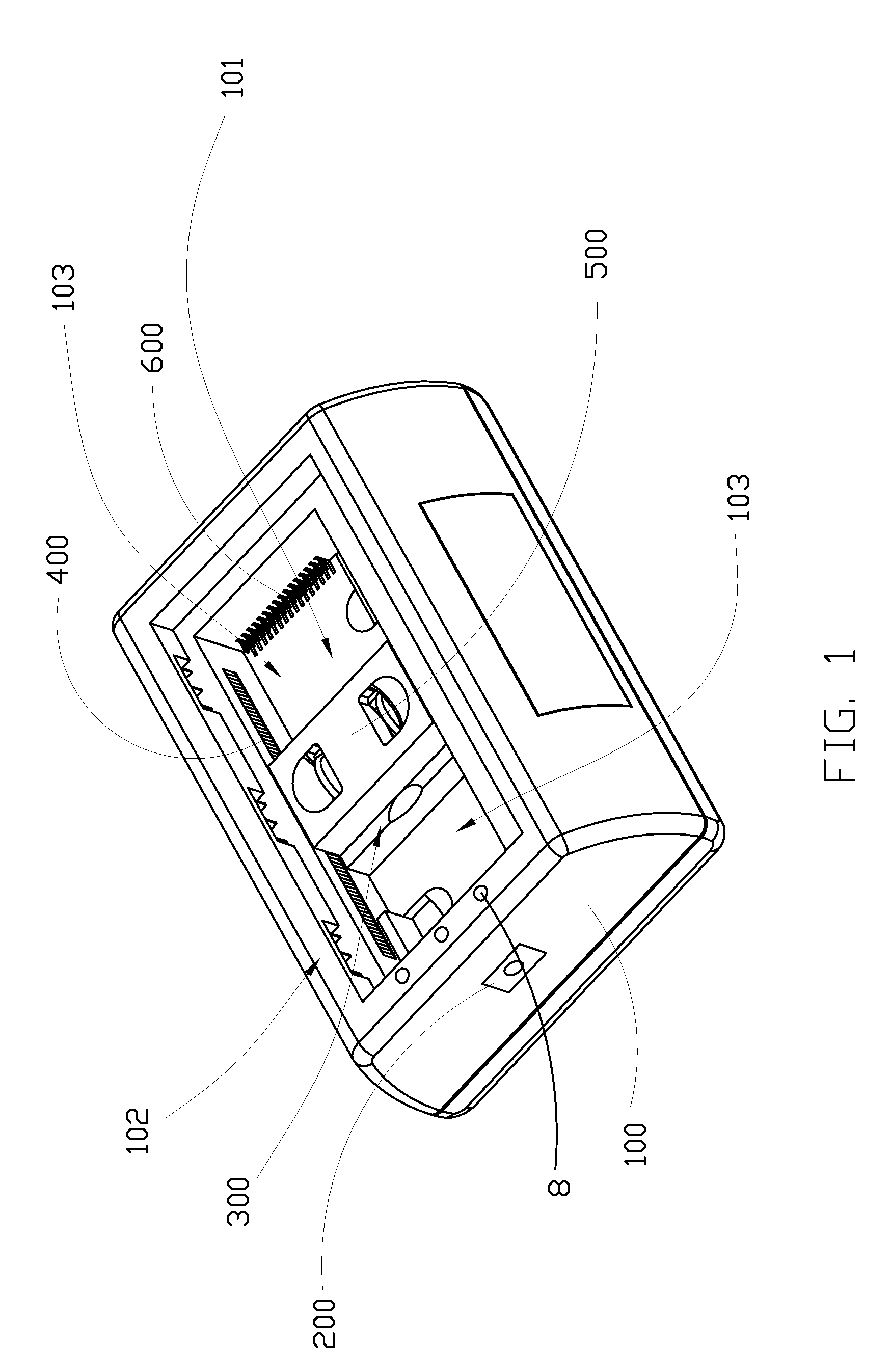
[0029]Referring to FIG. 1 to FIG. 3, FIG. 4A to FIG. 4F of the drawings, a multi-battery charger according to a preferred embodiment of the present invention is illustrated, in which the multi-battery charger comprises a charger case 100, and a multi-battery charging module. The multi-battery charger is for charging at least one rechargeable battery, such as a rechargeable battery for a conventional cellular phone, and has a first and a second battery terminal.
[0030]The charger case 100 comprises a plurality of electrically neutral charging terminals 600 spacedly provided thereon as multi-contact terminals of the charger case 100, and an electric input terminal 200 adapted for electrically connecting with an external DC power source.
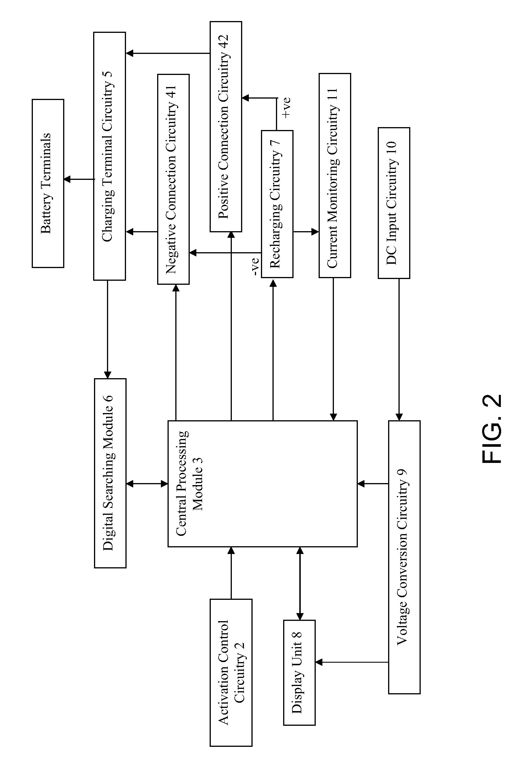
[0031]The multi-battery charging module is provided in the charger case 100 to electrically communicate with the charging terminals 600, and comprises a recharging circuitry 7 and a polarity detection circuitry. The recharging circuitry 7 has a positive ...
PUM
 Abstract
Description
Claims
Application Information