Cervical dilator and methods of use

a dilator and cervical technology, applied in the field of cervical dilators, can solve the problems of laceration of the cervix, difficulty for the clinician to assess whether the lesser resistance encountered is more effective, and the tenaculum to tear through the tissue and lacerate the cervix, so as to reduce the possibility of injury or harm to the patien

Inactive Publication Date: 2008-03-27
FEMSUITE
View PDF28 Cites 16 Cited by
  • Summary
  • Abstract
  • Description
  • Claims
  • Application Information

AI Technical Summary

Benefits of technology

[0027]In view of the foregoing, it is an object of the present invention to provide apparatus and m

Problems solved by technology

While this dilation procedure is relatively simple, complications are common.
Consequently, the clinician must apply greater pressure on the dilator rods, both causing the tenaculum to tear through the tissue and lacerate the cervix, and making it difficult for the clinician to assess whether the lesser resistance encountered at the end of the procedure is caused by the successful dilation of the cervix or by a perforation of the uterine wall.
As the hysteroscope became employed with greater frequency during routine gynecological practice, perforations became both more likely and more dangerous.
Uterine sounding is often performed contemporaneously with cervical dilation and requires the insertion of a probe inside the uterus until the fondus of the uterus is felt, further increasing the risk of uterine perforations.
Gutnick's invention, however, does not resolve the problem of uterine perforations and also provides no direct measurements of cervical dilation, which may lead to an excessive expansion of the cervical canal and to related damages.
Ghodsian's invention still does not resolve the problem of avoiding perforations during the sounding of the uterus, and requires a multi-step dilation process based on the deployment of multiple balloons.
Ogita's invention still does not solve the problem of avoiding uterine perforations and of obtaining a uniform and measurable cervical expansion, because it appears to be structured and operated for preventing a premature birth in pregnant women, rather than for sounding the uterus and for expanding the cervix in a gradual and uniform manner.
U.S. Pat. No. 4,976,692 and U.S. Published Application No. 2006/0058831, both to Atad, also disclose multi-balloon cervical cathe

Method used


Image

  • Cervical dilator and methods of use
  • Cervical dilator and methods of use
  • Cervical dilator and methods of use

Examples


first embodiment

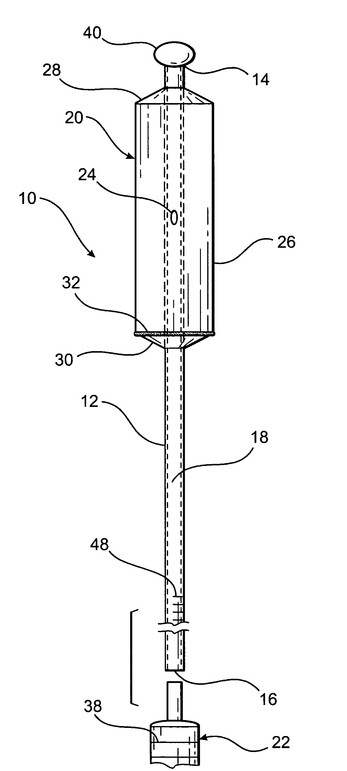
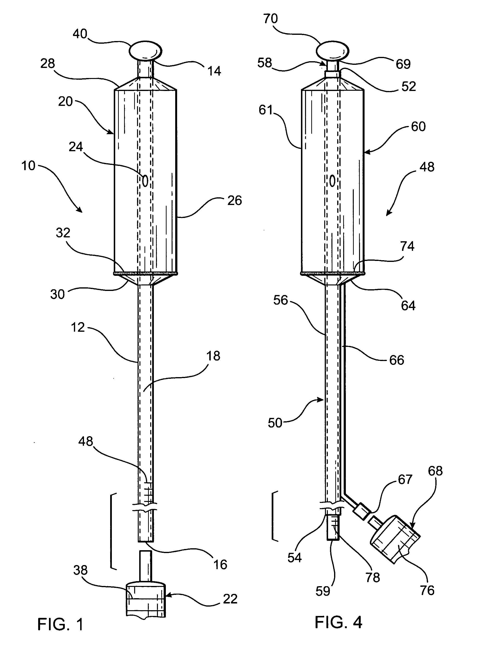
[0057]Referring first to FIG. 1, a cervical dilator constructed in accordance with the principles of the present invention is described. In its most basic configuration, cervical dilator 10 includes tubular member 12, balloon 20 and rounded cap 40.

[0058]More particularly, tubular member 12 has a hollow, elongated shape that includes distal end 14, proximal end 16, and lumen 18 extending therebetween. Balloon 20 is disposed at the distal portion of tubular member 12 and is also in fluid communication with proximal end 16. When injection device 22 (for example, a syringe) is connected to proximal end 16, a fluid, either liquid or gaseous, can be transmitted from injection device 22 to balloon 20 through lumen 18. Aperture 24 in lumen 18 provides fluid communication between lumen 18 and the inner part of balloon 20, enabling the inflation of balloon 20. In a variant of the present embodiment, lumen 18 does not extend from proximal end 16 to distal end 14, but extends instead only from ...

second embodiment

[0073]Referring now to FIG. 4, a cervical dilator constructed according to the principles of the present invention is described. Cervical dilator 48 comprises outer tubular member 50 having first lumen 56 extending between distal end 52 and proximal end 54. Inner member 58 is positioned within first lumen 54 and is longer than outer member 50, reciprocating within and extending out of first lumen 54 when a longitudinal pressure is applied to proximal end 59 of inner member 58.

[0074]Balloon 60 is disposed on the distal portion of outer member 50, and has a shape adapted to be received in cervical canal 24. Balloon 60 is preferably manufactured from a non-compliant material and will expand to have a shape comprising central cylindrical portion 61, distal tapered end portion 62 and proximal end tapered portion 64. As for the previously described embodiment, one skilled in the art will recognize that balloon 60 may be manufactured to expand to different shapes, all suitable for expandin...

third embodiment

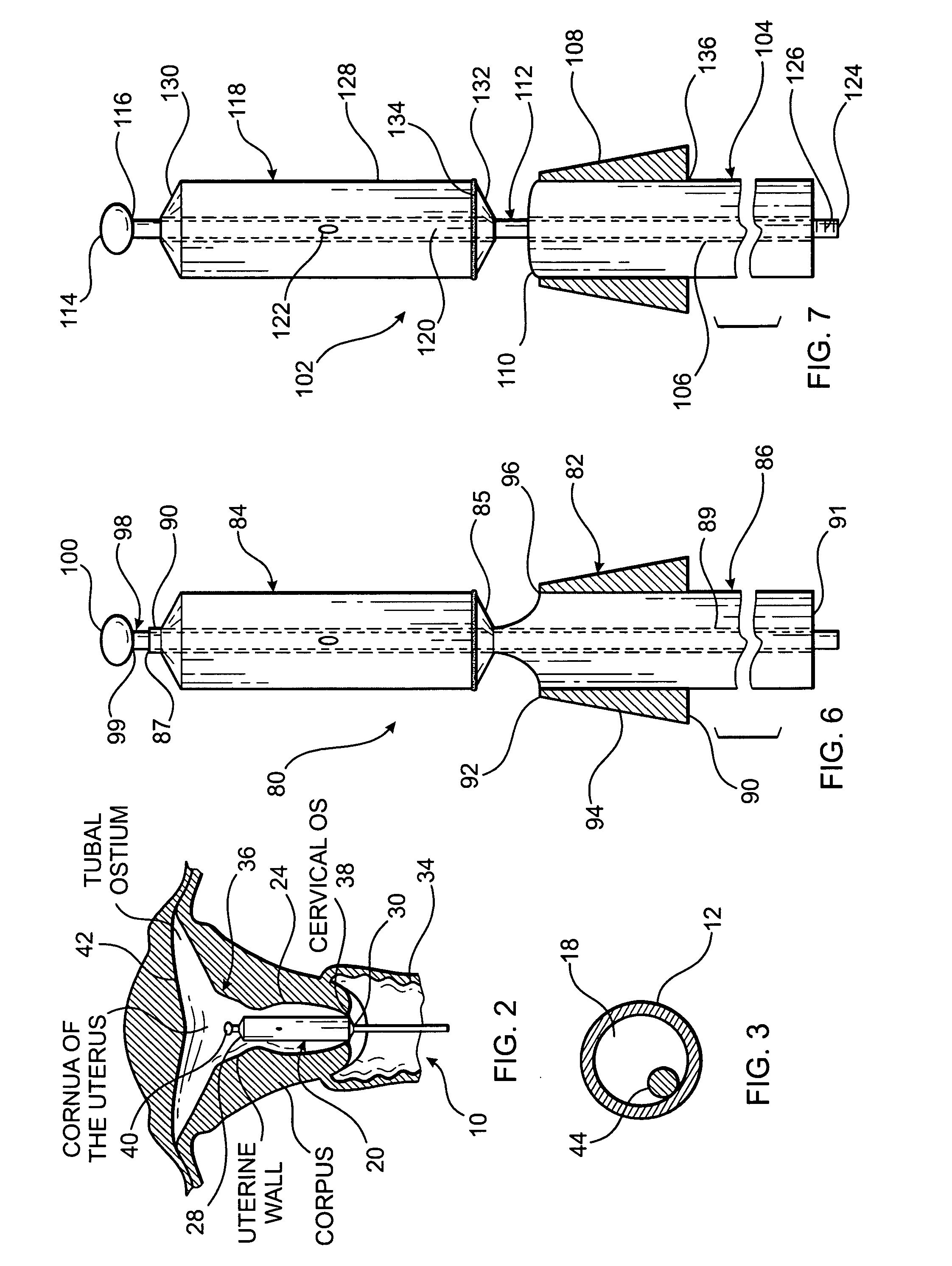
[0085]Referring now to FIG. 6, a cervical dilator constructed according to the principles of the present invention is described. Cervical dilator 80 has a structure that is similar to the previously described embodiments 10 and 48, but that further includes applicator member 82. The purpose of applicator member 82 is to enable the clinician to maintain cervical os 38 in a dilated position after balloon 84 has been deflated and retracted from cervical canal 24.

[0086]Cervical dilator 80 includes outer member 86 having proximal portion 88, that supports applicator member 82, and distal portion 90, that supports balloon 84. Longitudinal lumen 89 extends between distal end 87 and proximal end 89 of outer tubular member 86.

[0087]Applicator member 82 is preferably frustoconical in shape and includes major base 90, oriented proximally, minor base 92, oriented distally, and lateral wall 94. Lumen 96 extends longitudinally between major base 90 and minor base 92 of applicator member 82, and o...


PUM


Abstract

In one embodiment, a cervical dilator includes a tubular member having a rounded cap disposed at the distal end, a balloon disposed on the distal portion, a lumen extending longitudinally within the tubular member, and a flexible wire attached to the wall of the lumen. The cervical dilator may be extended inside the uterus of a patient for sounding, and the tubular member will bend but not snap if excessive pressure is applied against a uterine wall, sliding away from the point of contact. The balloon is then properly positioned inside the cervical canal and gradually inflated. In other embodiments, a plurality of tubular members may be included, each reciprocating within another, and one or two applicator members may also be provided, to retain the cervix in position before and after dilation.

Description

FIELD OF THE INVENTION[0001]The present invention relates to cervical dilators for sounding the uterine cavity and for expanding the cervical canal. More particularly, the present invention relates to cervical dilators that minimize the risk of uterine perforations during sounding and that provide for a gradual, atraumatic expansion of the cervical canal.BACKGROUND OF THE INVENTION[0002]The cervix of a non-pregnant, reproductive age woman is a dense, yet distensible organ that has a resting diameter of 3-4 mm. Gynecological and obstetrical procedures often require a dilation of the cervix, to inspect visually the cervical and uterine regions and to access the uterine cavity with different types of medical instruments.[0003]The cervix ordinarily responds to outward pressure by expanding within anatomical limits, but such pressure must be applied gradually to minimize damage. When pressure is continuously applied for even a short period of time, the cervix will remain temporarily in t...

Claims


Application Information

Patent Timeline
IPC IPC(8): A61B5/103
CPCA61B1/32
Inventor FEUER, GERALDSANDERS, GERALD J.
Owner FEMSUITE
Why Eureka
Try Eureka