

Work feeding and conveying mechanism for a planing machine
- Summary
- Abstract
- Description
- Claims
- Application Information
AI Technical Summary
Benefits of technology
Problems solved by technology
Method used
Image

Examples
Embodiment Construction
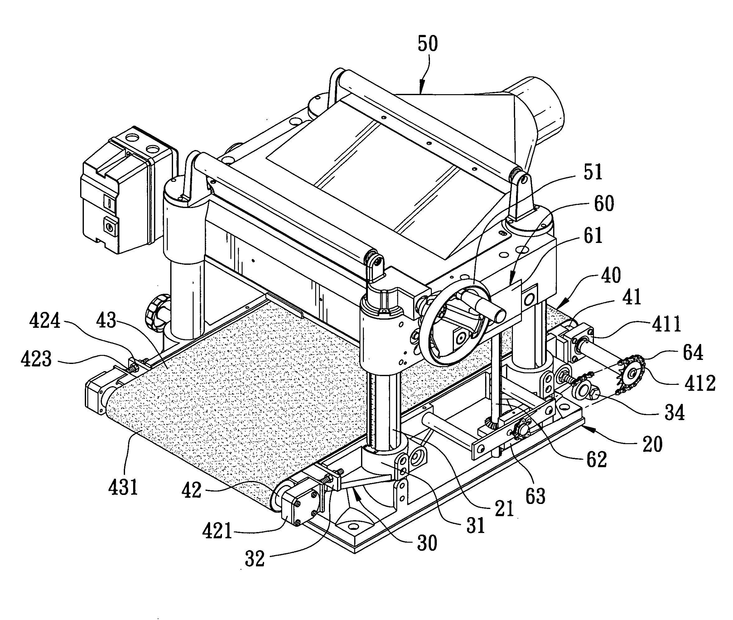
[0016]A first preferred embodiment of a work piece feeding and conveying mechanism for a planing machine in the present invention, as shown in FIGS. 3-7, includes a planing table 20, an intermediate base 30, a conveying device 40, an upper base 50 and a transmission device 60 as main components combined together.
[0017]The planing table 20 with a flat upper surface has its periphery fixed with four threaded rods 21 spaced apart and extending upward vertically and its interior installed with a motor (not shown) for producing power.
[0018]The intermediate base 30 has its periphery formed with four projections spaced apart and respectively bored with a vertical threaded hole 31 to be respectively and pivotally around the lower end of each threaded rod 21 of the planing table 20. The intermediate base 30 further has its rear end provided with a projecting block 32 having its opposite ends respectively extending out of the intermediate base 30. The projecting block 32 has its opposite ends...
PUM
 Abstract
Description
Claims
Application Information