Method and Apparatus for Utilizing Time Division Multiple Waveform Transmitting

a time division and waveform technology, applied in the field of geophysical prospecting, can solve the problems of insufficient frequency bandwidth, insufficient energy distribution of transmitted frequencies, and insufficient frequency bandwidth of available waveforms to probe a desired range of depths

Active Publication Date: 2009-10-01
EXXONMOBIL UPSTREAM RES CO
View PDF5 Cites 29 Cited by
  • Summary
  • Abstract
  • Description
  • Claims
  • Application Information

AI Technical Summary

Problems solved by technology

However, because of the cost of operating the aircraft or vessel, a pass over the survey line may be performed only once.
This single pass approach using waveforms currently available does present some problems with the frequency bandwidth, the efficient transmission of energy at desired frequencies, and the energy distribution of the transmitted frequencies.
For instance, available waveforms may not provide a frequency bandwidth wide enough to probe a desired range of depths.
As such, noises may degrade data quality because the transmitted energy is limited and not strong enough to generate measurable responses at some frequencies.

Method used


Image

  • Method and Apparatus for Utilizing Time Division Multiple Waveform Transmitting
  • Method and Apparatus for Utilizing Time Division Multiple Waveform Transmitting
  • Method and Apparatus for Utilizing Time Division Multiple Waveform Transmitting

Examples


Embodiment Construction

[0026]In the following detailed description, the specific embodiments of the present invention will be described in connection with its preferred embodiments. However, to the extent that the following description is specific to a particular embodiment or a particular use of the present techniques, this is intended to be illustrative only and merely provides a concise description of the exemplary embodiments. Accordingly, the invention is not limited to the specific embodiments described below, but rather, the invention includes all alternatives, modifications, and equivalents falling within the true scope of the appended claims.

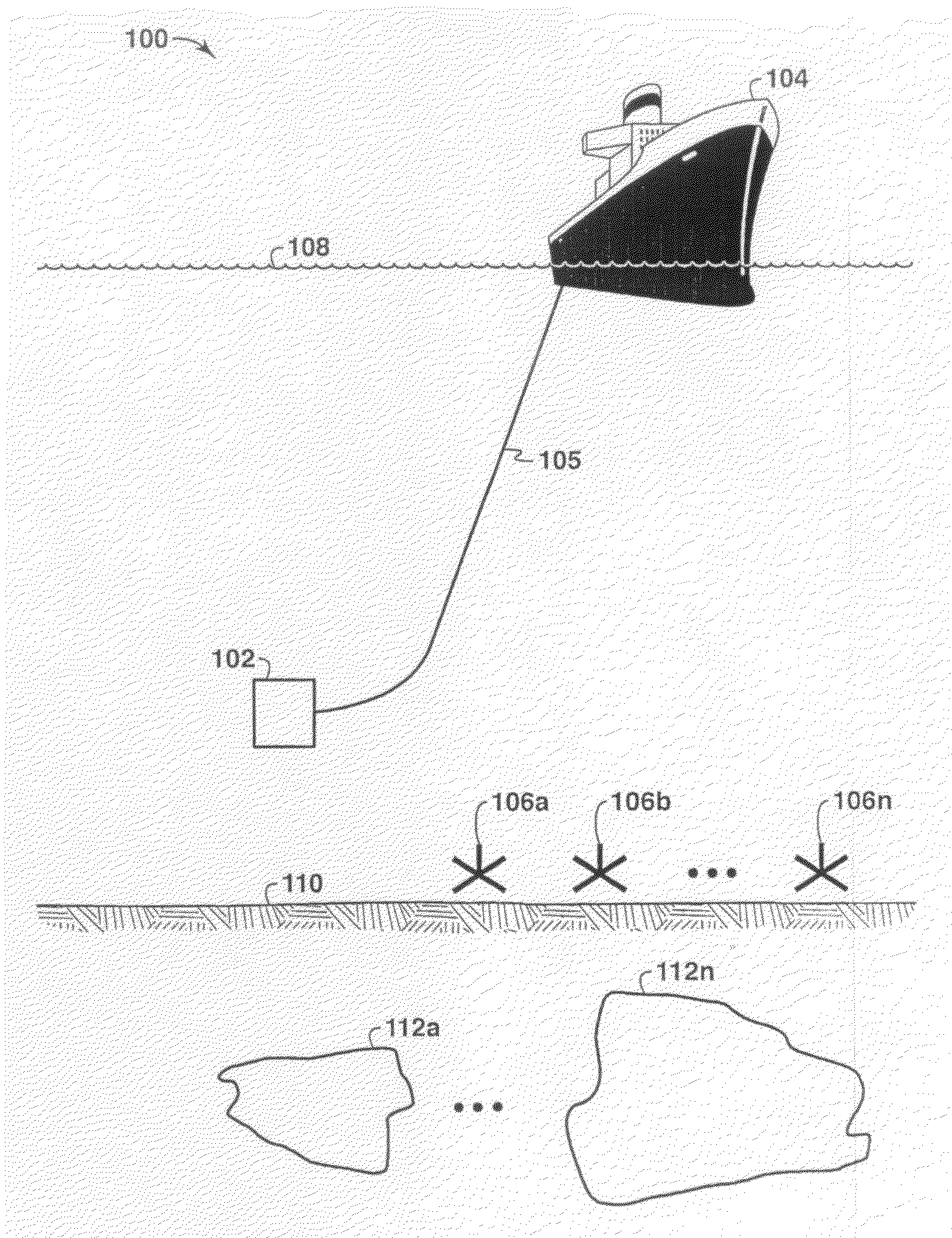
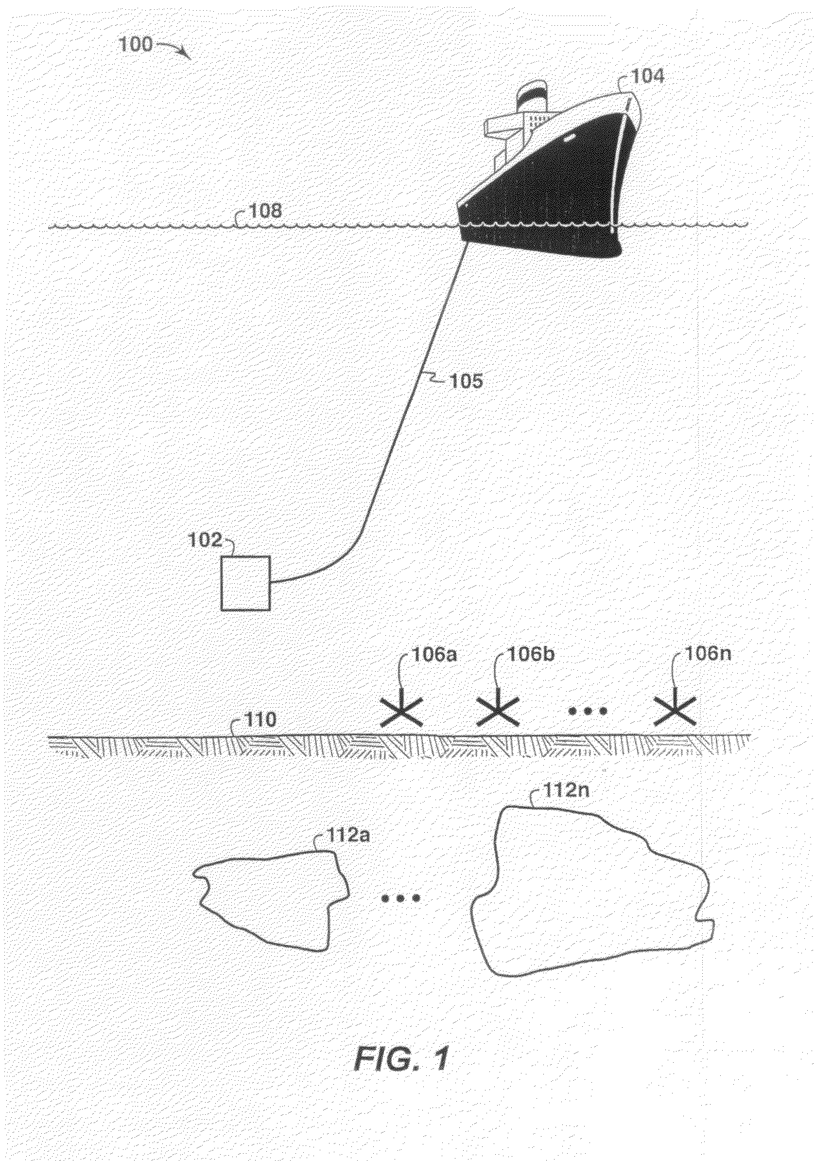
[0027]The present technique is directed to a method and system that optimize transmitter waveforms. Under the present techniques, which may be referred to herein as Time Division Multiple Waveform Transmitting (TDMWT), a transmitter transmits a compound waveform composed of different base waveforms at designated time intervals rather than one base waveform. T...


PUM


Abstract

A method and apparatus of constructing a signal for a controlled source electromagnetic survey is described. In one embodiment, a method is described that includes determining a first waveform and a second waveform, the first waveform and second waveform related to a combined frequency spectrum and bandwidth associated with a geophysical survey line. Then, a signal is constructed by sequencing the first waveform with the second waveform. This signal may be utilized in a transmitter, which may be pulled by a vessel along the geophysical survey line.

Description

[0001]This application claims the benefit of U.S. Provisional Application No. 60 / 726,902 filed on Oct. 14, 2005.FIELD OF THE INVENTION[0002]This invention relates generally to the field of geophysical prospecting and, more particularly, to electromagnetic surveys. Specifically, the invention relates to the field of controlled-source electromagnetic surveys for geophysical applications, and transmitter waveforms for generating controlled-source electromagnetic fields.BACKGROUND OF THE INVENTION[0003]This section is intended to introduce the reader to various aspects of art, which may be associated with exemplary embodiments of the present techniques, which are described and / or claimed below. This discussion is believed to be helpful in providing the reader with information to facilitate a better understanding of particular aspects of the present techniques. Accordingly, it should be understood that these statements are to be read in this light, and not necessarily as admissions of pr...

Claims


Application Information

Patent Timeline
Patent Type & Authority Applications(United States)
IPC IPC(8): G01V3/00
CPCG01V3/12G01V3/083
Inventor LU, XINYOUHORNBOSTEL, SCOTT C.WILLEN, DENNIS E.
Owner EXXONMOBIL UPSTREAM RES CO
Why Eureka
Try Eureka