Device for a Vibration Generator

Inactive Publication Date: 2010-09-09
ABI ANLAGENTECHN BAUMASCHEN INDBEBEDARF
View PDF7 Cites 3 Cited by
  • Summary
  • Abstract
  • Description
  • Claims
  • Application Information

AI Technical Summary

Benefits of technology

[0041]In order to use the device according to the invention with a vibration generator, it may be advantageous that the devi

Problems solved by technology

In contrast thereto, it is disadvantageous in the case a means generating initial tension has a large travel.
This results in an increased weight, enlarged constructional space and larger travel.
The latter is also disadvantageous in so far as larger travel also leads to an enlarged overall configuration of the vibration generator; further, it requires more effort to connect and attach, respectively, components used with the vibration generator (e.g

Method used


Image

  • Device for a Vibration Generator
  • Device for a Vibration Generator
  • Device for a Vibration Generator

Examples


Embodiment Construction

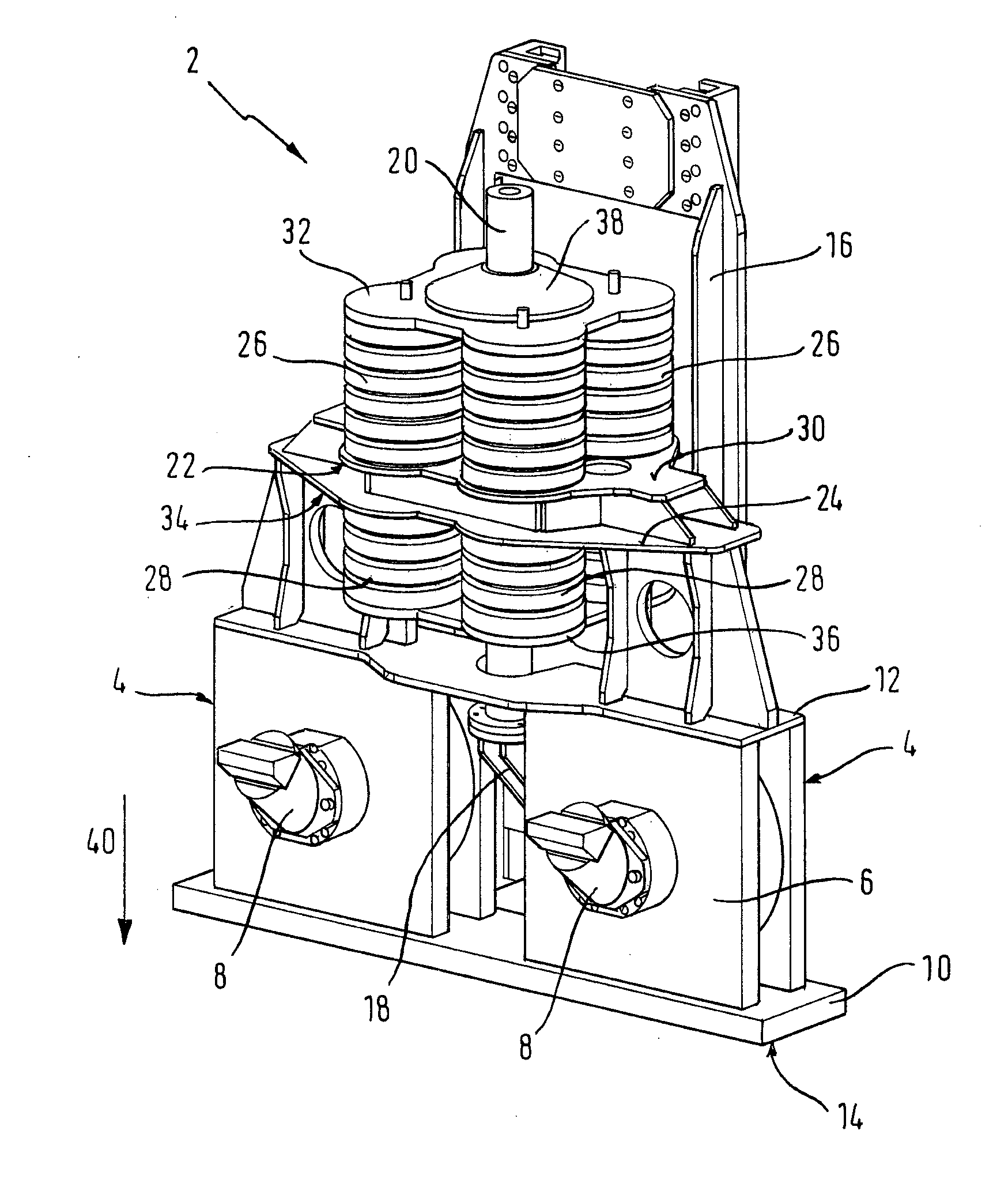
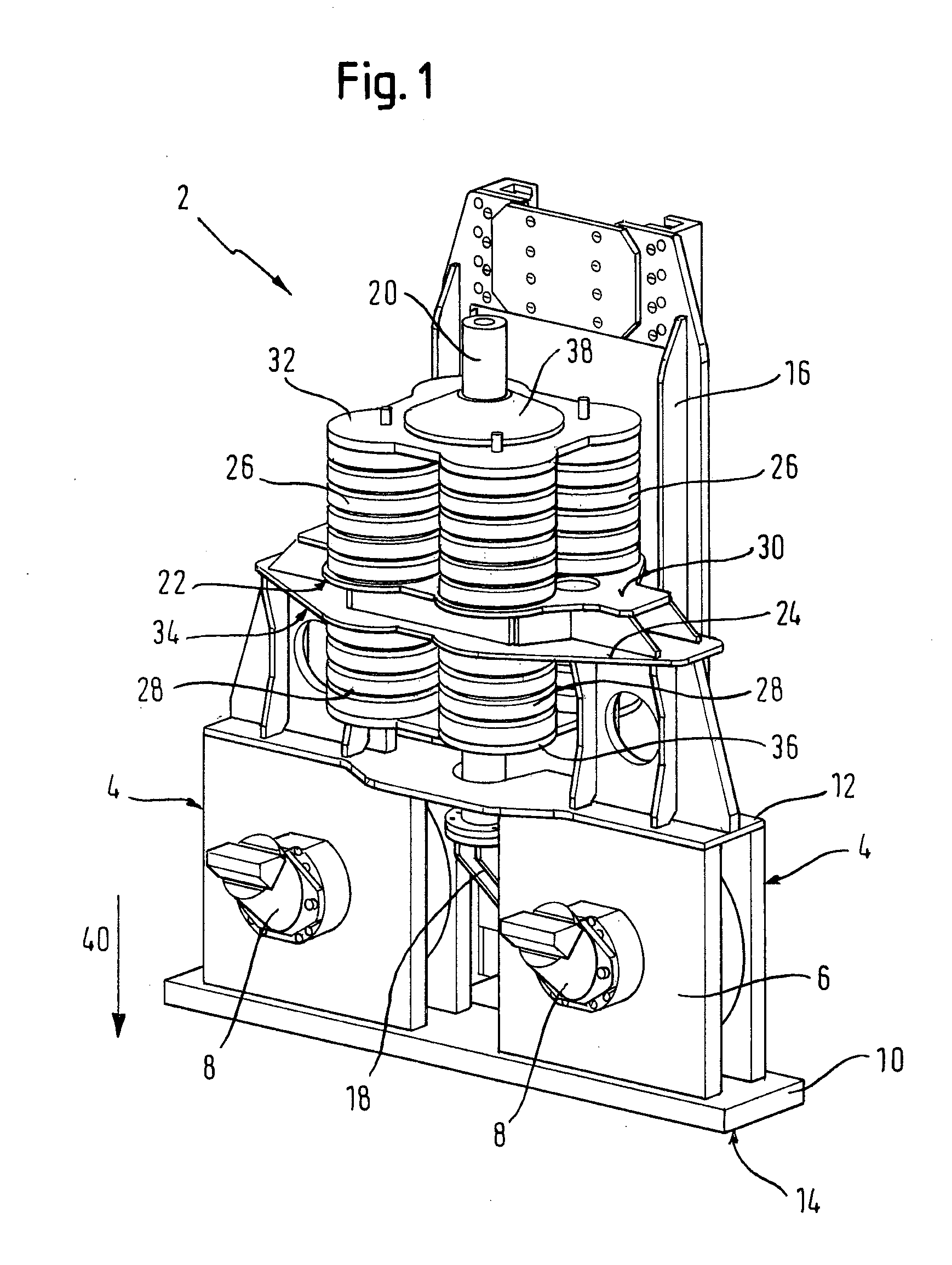
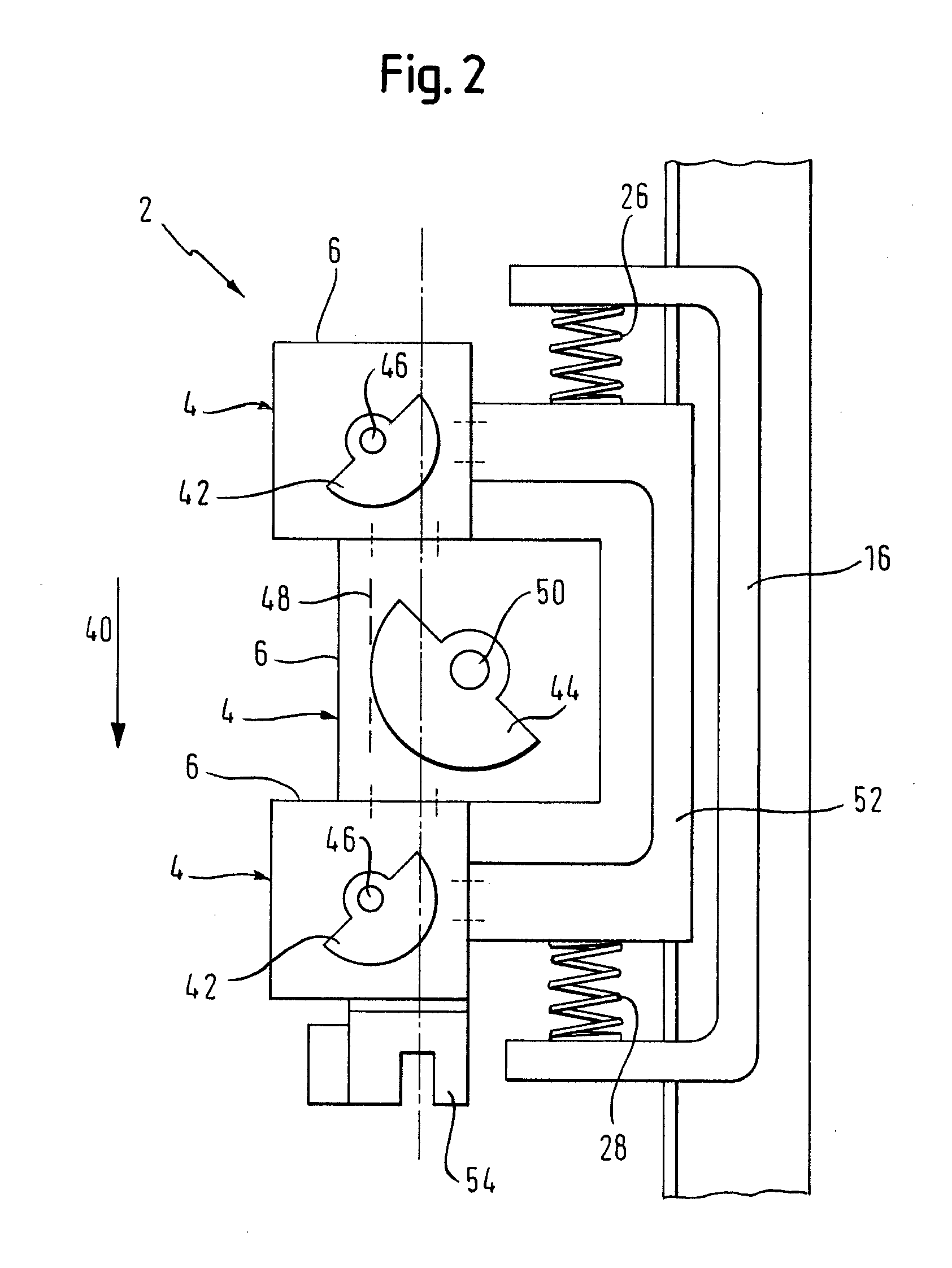
[0054]With reference to FIGS. 1 and 2, in the following preferred embodiments of vibration generators, which may be provided for use with the present invention, are described.

[0055]FIG. 1 shows an embodiment of a vibration generator, which as a whole is designated by 2. The vibration generator 2 comprises two excitation modules 4, which are, for the sake of simplicity, illustrated as being of the same type, which however can differ.

[0056]The excitation modules 4 respectively comprise an own housing 6, in which a rotatable axle (not shown) is arranged, on which one or more unbalanced weights (not shown) are mounted.

[0057]Further, the excitation modules 4 respectively comprise, on their housings 6, a rotation drive 8 for the respective axle.

[0058]The excitation modules 4 are connected with each other via a connection device. According to FIG. 1, the connection device comprises a plate-like and, respectively, sheet-like connection element 10, on which the, according to the drawing, low...


PUM

PropertyMeasurementUnit
Timeaaaaaaaaaa
Forceaaaaaaaaaa
Resilienceaaaaaaaaaa

Abstract

A device for a vibrator, including at least one resilient element, with a force/travel curve having a first region, at least approximately given by an equation of formula K=a+b*W, where K is the spring force of the at least one resilient element, W is the spring travel and a and b are number greater than zero and a vibrator including such a device.

Description

FIELD OF THE INVENTION[0001]The present invention generally relates to vibration generators and, particularly, to a device for a vibration generator for providing initial tension and / or damping in a vibration generator.BACKGROUND OF THE INVENTION[0002]Vibration generators are used, for example, for driving piling material into the ground. Sometimes, such vibration generators are also referred to as vibrators. A vibration generator generates forces to be transferred to piling material by means of unbalanced weights arranged on axles. Upon rotation, the individual unbalanced weights generate forces, which mutually complement, increase each other in the direction, in which forces are transferred onto piling material (e.g. in driving direction); at least in directions oblique thereto, they cancel each other out.[0003]In order to support and increase, respectively, forces of a vibration generator in one direction (e.g. in driving direction), it is possible to generate an initial tensioni...

Claims


Application Information

Patent Timeline
IPC IPC(8): B06B1/10E02D7/18F16F1/36
CPCY10T74/18344B06B1/161
Inventor KLEIBL, ALBRECHTHEICHEL, CHRISTIAN
Owner ABI ANLAGENTECHN BAUMASCHEN INDBEBEDARF
Why Eureka
Try Eureka