Engaging structure for closet drawer

a technology for engaging structure and drawers, applied in the direction of furniture parts, door/window fittings, construction fastening devices, etc., can solve the problems of endangering the user, and achieve the effect of increasing the force exerted and enhancing the positioning

Inactive Publication Date: 2011-05-26
CHANG TING YU
View PDF8 Cites 73 Cited by
  • Summary
  • Abstract
  • Description
  • Claims
  • Application Information

AI Technical Summary

Benefits of technology

[0009]Another objective of the invention is to enhance the positioning effect between the engaging part and the stopping part. This is achieved by providing an elastic element on one side of the connecting part at the bottom of the fixing element. This elastic element provides has the effects of restoring the stopping part of the fixing element and increasing the force exerted by the stopping part on the stopping element.

Problems solved by technology

In this case, the drawer 4 easily slides out of the closet 5, endangering its user.

Method used


Image

  • Engaging structure for closet drawer
  • Engaging structure for closet drawer
  • Engaging structure for closet drawer

Examples


first embodiment

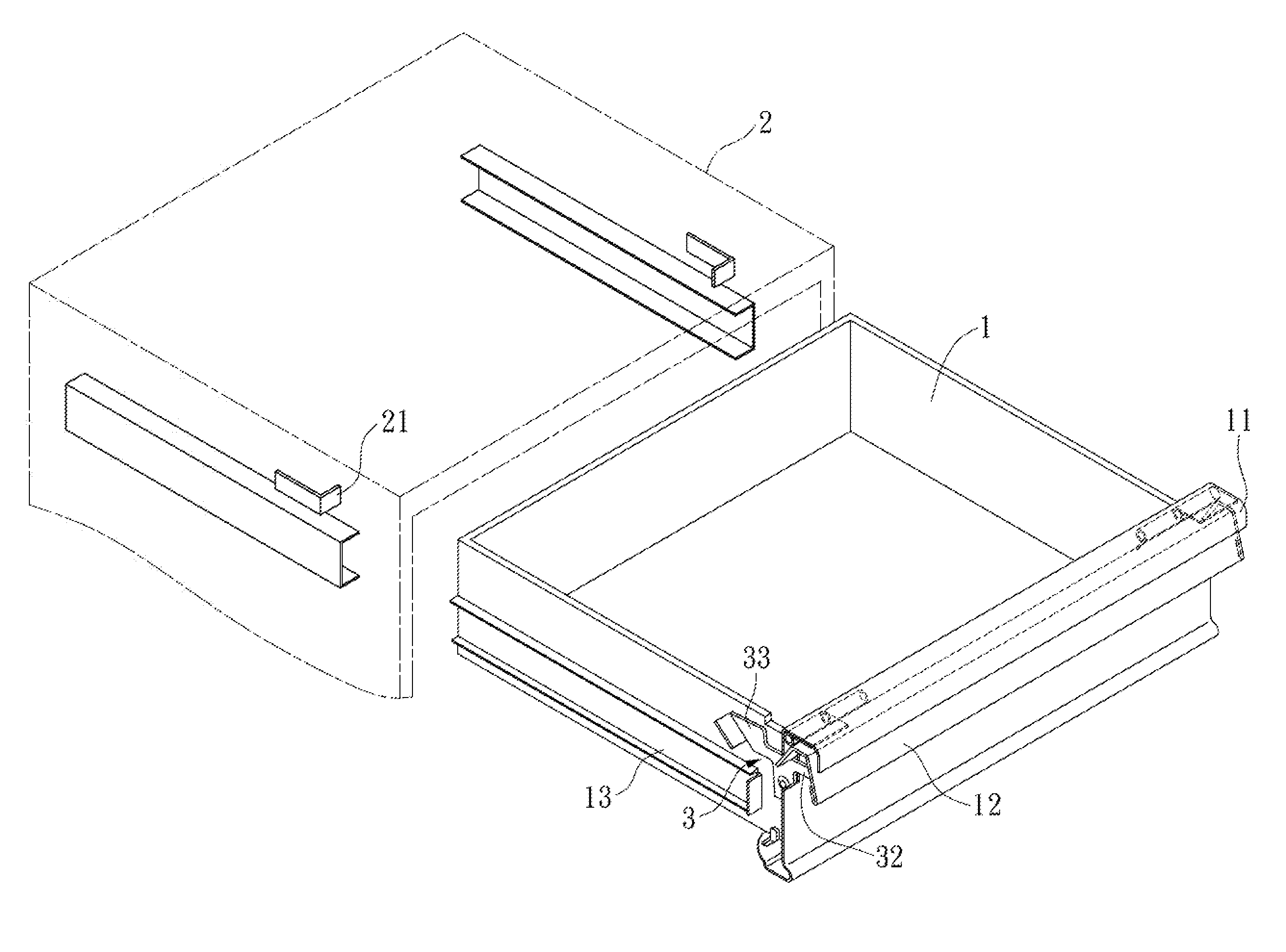
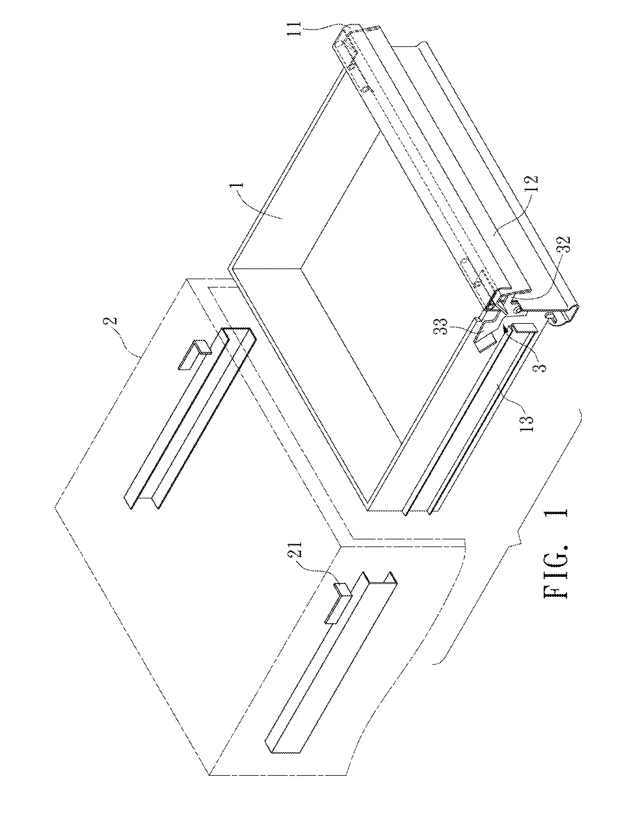
[0024]the disclosed engaging structure for the drawer of a closet is described with reference to FIGS. 1 to 3. The disclosed structure includes: a holder 11, a lift handle 12, and at least one fixing element 3.

[0025]The holder 11 is disposed on the front side of a drawer 1 for the user to hold while drawing and pushing the drawer 1 into and from a closet 2. In this embodiment, the holder 11 is horizontally disposed along the top edge in front of the drawer 1. Moreover, the holder 11 is an arc protrusion.

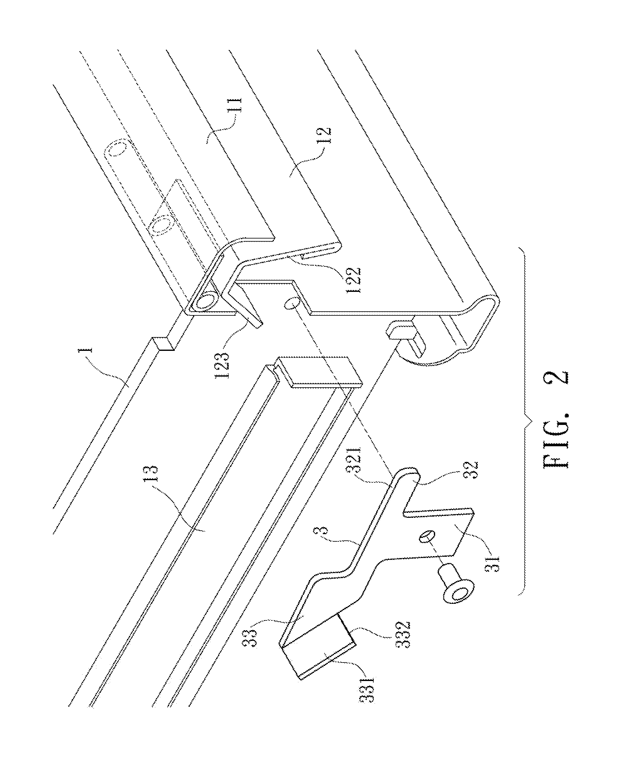
[0026]The lift handle 12 is also horizontally disposed in front of the drawer 1, under the holder 11. In this embodiment, the lift handle 12 has a pivotal connection part 121. The top edge of the pivotal connection part 121 pivotally connects with the drawer 1. The lift handle 12 further has a lifting part 122 and a pushing part 123. The lifting part 122 connects to the outer side edge of the pivotal connection part 121, and extends obliquely downward from the pivotal connection part...

second embodiment

[0030]Of course, the invention has many other embodiments that only vary in details. Please refer to FIGS. 5 to 8 for the invention. The pushing part 123 of the lift handle 12 protrudes downward by an appropriate length. It further bends and protrudes outward with a pushing part 124. Besides, the first guiding part 32 on one end of the fixing element 3 protrudes upward with a second guiding part 34, forming an L-shaped guiding part. The inner surface of the second guiding part 34 forms a slide guiding surface 341. The bottom end of the pushing part 124 urges against the slide guiding surface 341 of the second guiding part 34. As the pushing part 124 of the lift handle 12 pushes the second guiding part 34, the lift handle 12 can slide more smoothly with respect to the fixing element 33. Moreover, a stopping element 23 is disposed on an outer slide rail 22 of the closet 2 corresponding to the slide rail 13 of the drawer 1, in correspondence with the stopping end 332 of the engaging pa...


PUM


Abstract

An engaging structure of the drawer of a closet includes a fixing element on any one of the two opposite sides of the drawer that have sliding rails. One end of the fixing element is provided with a first guiding part corresponding to the end edge of the lift handle disposed on the front side of the drawer. The other end of the fixing element has an engaging part to engage with a stopping part when the drawer is put into the closet. To pull or push the drawer out of or into the closet, the user uses the lift handle to control the engagement or departure between the engaging part and the stopping part.

Description

BACKGROUND OF THE INVENTION[0001]1. Field of Invention[0002]The invention relates to an engaging structure of the drawer of a closet and, in particular, to an engaging structure that controls the positioning or departure of a drawer in or out of the closet.[0003]2. Related Art[0004]FIG. 9 shows an opening / closing structure of a conventional drawer. The front wall 41 of the drawer 4 is provided with a pulling element 42. The pulling element 42 connects to a lift handle 43 in the drawer 4. The lift handle 43 is pivotally connected to one sidewall of the drawer 4. The other end of the lift handle 43 has an engaging part 431. Inside the closet 5 there is a corresponding stop hole 51 for the engaging part 431 to engage. An elastic element 44 is disposed between the lift handle 43 and the front wall 41 of the drawer 4 for the lift handle 43 to restore its position after the drawer is pulled.[0005]As shown in the drawing, the pulling element 42 and the lift handle 43 are represented by the...

Claims


Application Information

Patent Timeline
Patent Type & Authority Applications(United States)
IPC IPC(8): A47B95/02A47B88/12
CPCE05B7/00E05C3/162E05B65/46
Inventor CHANG, TING-YU
Owner CHANG TING YU
Why Eureka
Try Eureka