Novel Implant Inserter Having a Laterally-Extending Dovetail Engagement Feature
What is AI technical title?
AI technical title is built by Patsnap AI team. It summarizes the technical point description of the patent document.
a technology of engagement feature and implant, which is applied in the field of implant inserter with laterally extending dovetail engagement feature, can solve the problem of not being able to ensure that the anterior surface of the implant bottoms out on the inserter tip
Active Publication Date: 2012-06-14
DEPUY SYNTHES PROD INC +1
View PDF9 Cites 106 Cited by
Summary
Abstract
Description
Claims
Application Information
AI Technical Summary
This helps you quickly interpret patents by identifying the three key elements:
Problems solved by technology
Method used
Benefits of technology
Benefits of technology
[0009]The instrument of the present invention is advantageous over conventional inserter instruments having threads and other known grabber features, which sometimes need to withstand impaction and may move upon insertion of a bone anchor or instruments through the device.
[0010]The dual angle nature of the present invention ensures that the implant is axially square and / or co-linear with the instrument and so further ensures that a larger surface area of the instrument absorbs any required impaction.
[0015]Optional elements on the inserter may include a knob, a drag adjustment screw, at least one protrusion, and a depth control member. The knob can be mechanically coupled to the outer sleeve for causing the outer sleeve and the forked inner shaft to be rotated about the frame. The drag adjustment screw can provide tension between the trigger mechanism and the forked inner shaft. The at least one protrusion can be located on the outer sleeve for slidably engaging a distraction instrument. The depth control member can be slidably coupled to the outer sleeve for providing a predetermined insertion depth of the implant.
[0021]The invention has many advantages. For example, the invention provides safe one-handed insertion of an implant into a prepared disc space. The invention reduces the amount of time required to complete the surgical procedure. The invention also provides for various manipulations of the implant without physically contacting the implant. For example, the invention can align an endplate of the implant radially and provide a lordotic angle for implantation. The invention can be used for packaging the implant, and the invention can be used to hold the implant during the implant sterilization process.
Problems solved by technology
Conventional inserters with chamfer features also do not take advantage of dissimilar angles at the interface in more than one plane, and so fail to ensure that the anterior surface of the implant bottoms out on the inserter grabber tip.
Method used
Image
Click on the blue label to locate the original text in one second.
Reading with bidirectional positioning of images and text.
Examples
Embodiment Construction
[0039]The foregoing and other objects, features and advantages of the invention will be apparent from the following more particular description of preferred embodiments of the invention, as illustrated in the accompanying drawings in which like reference characters refer to the same parts throughout the different views. The same number appearing in different drawings represents the same item. The drawings are not necessarily to scale, with emphasis instead being placed upon illustrating the principles of the invention.
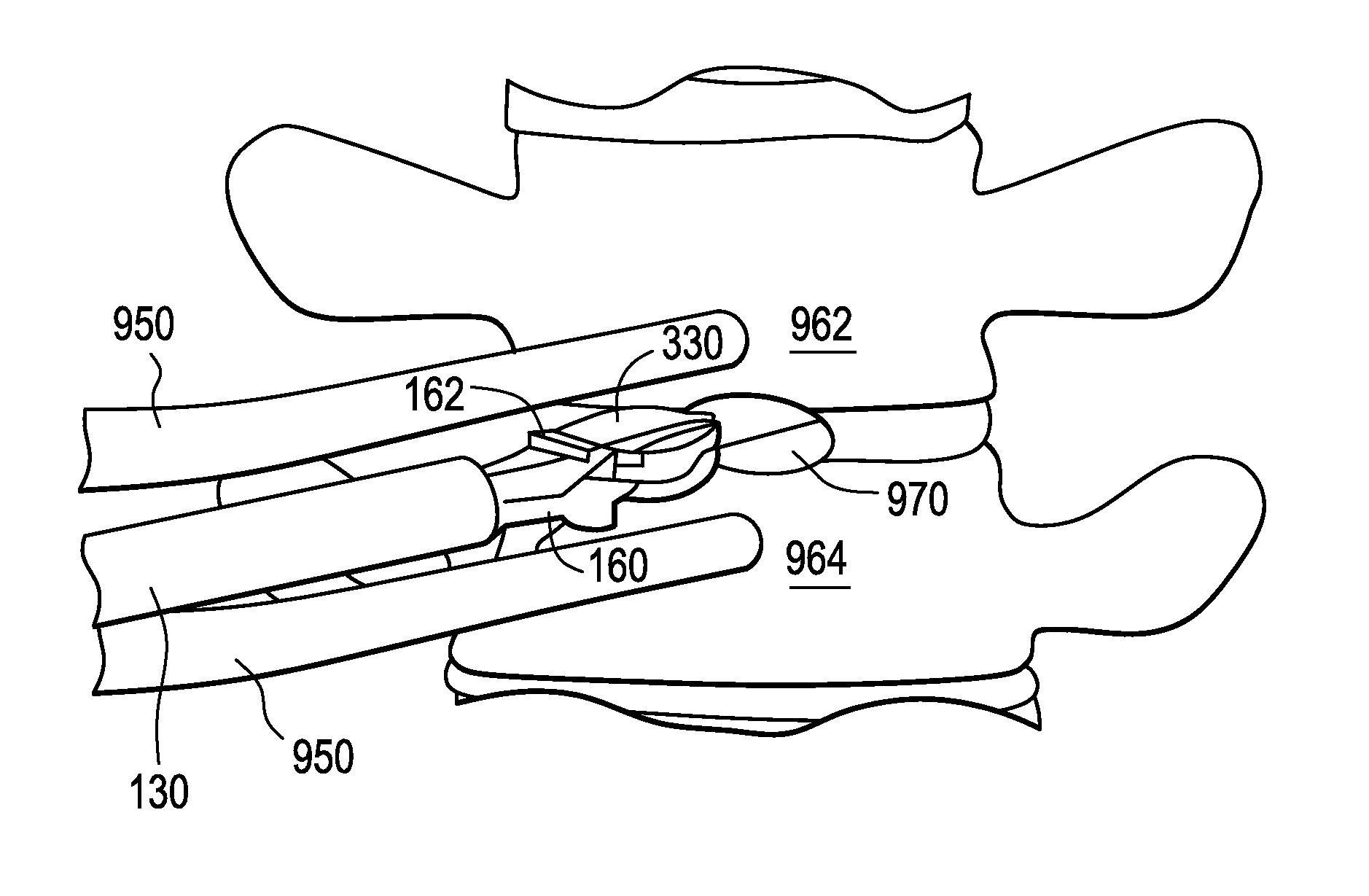
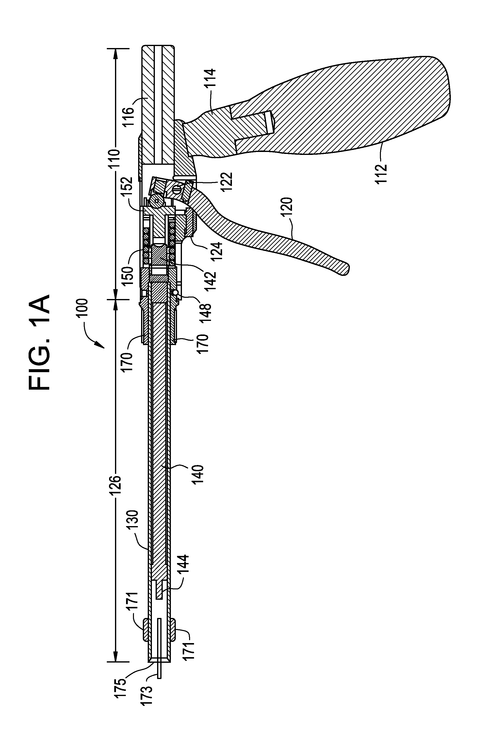
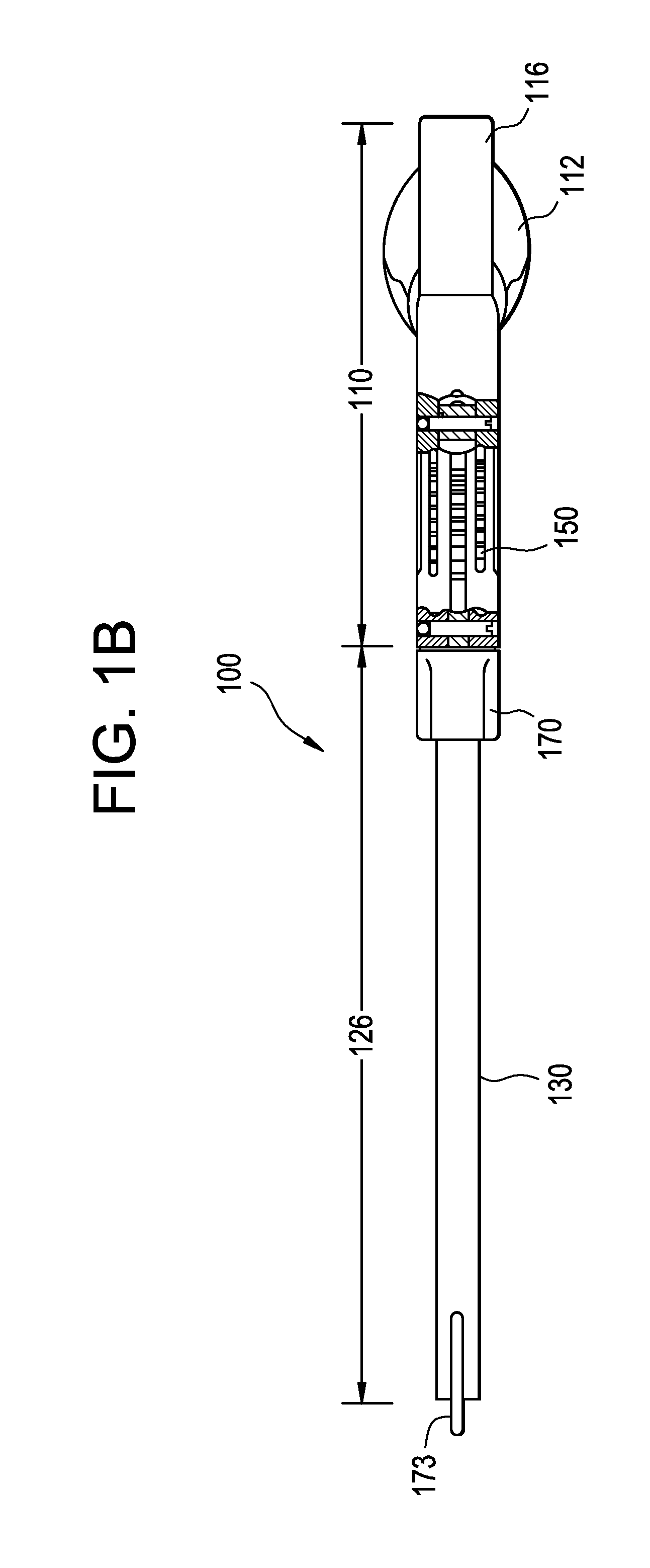
[0040]In general, the present invention is related to an apparatus and a method for safely inserting an implant into a spine. The implant can be an artificial disc or spinal fusion cage, or a spinal plate. Referring to FIGS. 1A and 1B, insertion instrument 100 is shown in a side cross-sectional view and a plan view, respectively. Insertion instrument 100 includes a frame or driver body assembly 110, an actuator assembly 126 and a forked inner shaft 160 (FIG. 2A-2C). In...
PUM
Abstract
A spinal implant inserter having a) an outer sleeve having a bore, and b) a forked inner shaft having a proximal rod and a pair of distal tynes extending therefrom, each distal tyne comprising an engagement feature having a laterally-extending dovetail feature. An assembly comprising the implant inserter and an implant having a pair of mating dovetail features.
Description
CONTINUING DATA[0001]This application claims priority from U.S. Ser. No. 61 / 385,959, filed on Sep. 23, 2010, and entitled “Stand Alone Intervertebral Fusion Device ” (DEP6341USPSP), and is related to non-provisional U.S. Ser. No. 13 / 237,233, filed on Sep. 20, 2011, entitled “Stand Alone Intervertebral Fusion Device” (DEP6341USNP), the specifications of which are incorporated by reference in their entireties.[0002]This application claims priority from U.S. Ser. No. 61 / 466,309, filed on Mar. 22, 2011, and entitled “Novel Implant Inserter Having a Laterally-Extending Dovetail Engagement Feature” (DEP6392USPSP), and from U.S. Ser. No. 13 / 237,200, filed on Sep. 20, 2011, and entitled “Novel Implant Inserter Having a Laterally-Extending Dovetail Engagement Feature” (DEP6392USNP), the specifications of which are incorporated by reference in their entireties.[0003]This application claims priority from U.S. Ser. No. 61 / 466,321, filed on Mar. 22, 2011, and entitled “Fusion Cage with In-Line S...
Claims
Application Information
Patent Timeline
Application Date:The date an application was filed.
Publication Date:The date a patent or application was officially published.
First Publication Date:The earliest publication date of a patent with the same application number.
Issue Date:Publication date of the patent grant document.
PCT Entry Date:The Entry date of PCT National Phase.
Estimated Expiry Date:The statutory expiry date of a patent right according to the Patent Law, and it is the longest term of protection that the patent right can achieve without the termination of the patent right due to other reasons(Term extension factor has been taken into account ).
Invalid Date:Actual expiry date is based on effective date or publication date of legal transaction data of invalid patent.
Patent Type & AuthorityApplications(United States)

