Enhanced compatibility for a linkage mechanism

Active Publication Date: 2012-11-29
L & P PROPERTY MANAGEMENT CO
View PDF41 Cites 58 Cited by
  • Summary
  • Abstract
  • Description
  • Claims
  • Application Information

AI Technical Summary

Benefits of technology

[0008]Generally, embodiments of the present invention seek to provide a simplified, compact linkage mechanism that can be adapted to essentially any type of seating unit. In particular embodiments, the present invention seeks to provide a linkage mechanism that can be assembled to a compact motor and that can be adapted to essentially any type of seating unit. In operation, the compact motor in concert with the linkage mechanism can achieve full movement of the seating unit between the closed, extended, and reclined positions. The compact motor may be employed in a proficient and cost-effective manner to adjust the linkage mechanism without creating interference or other disadvantages (e.g., preclusion of adaption to high-leg models) appearing in conventional designs that are inherent with automation.
[0010]In another instance, the base unit may accommodate a set of parallel-spaced crossbeams that accommodate a motor in order to provide an automated version of the linkage mechanism. Alternatively, a bolt-on tube and manual adjustment assembly may be provided to the base unit in place of the motor. Further, the base unit may be built to hold spring(s) in the manual version, while the automated version may be configured without the springs. Thus, because the right- and left-side base units are compatible with many types of seating units and a variety of styling options, this “compatibility” of the exemplary base units helps to reduce the total number of linkage mechanisms that are fabricated and shipped to furniture manufacturers and serves to satisfy a wide array of preferences within the marketplace.
[0013]In addition, the linkage mechanisms each include a roller link that is translatably coupled to a respective arm mounting plate via an interaction of tracks and rollers. Specifically, in an exemplary embodiment, the arm mounting plate is configured with forward and rearward guide slots whose tracks moveably direct translation of forward and rearward rollers, respectively, which are rotatably coupled to a roller link. In turn, the roller link is pivotably coupled to the seat rail via a pair of substantially parallel-spaced TV links. Thus, during adjustment of the linkage mechanisms, the cooperative operation of the tracks, rollers, and TV links allow for translation of the seat rail over the arm mounting plate such that the closed, extended, and reclined positions are properly achieved.

Problems solved by technology

However, these seating units require relatively complex linkage mechanisms to afford this capability.
The complex linkage assemblies limit certain design aspects utilized by furniture manufacturers.
In one instance, these linkage assemblies impose constraints on an upholstery designer's use of multiple styling features concurrently on an adjustable seating unit.
For instance, these linkage assemblies are bulky and require seating units to incorporate space-saving features (e.g., connecting the linkage mechanisms to a base resting on the floor), thereby hiding the linkage assemblies below the seat when in the closed position.
But, these space-saving features preclude a furniture designer from providing the seating unit configured with arms that rest either directly or indirectly, via the support of high legs, on an underlying surface.
In another instance, these linkage assemblies impose constraints on incorporating a single motor for automating adjustment between the positions mentioned above, and require two or more motors to accomplish automation of each adjustment.

Method used


Image

  • Enhanced compatibility for a linkage mechanism
  • Enhanced compatibility for a linkage mechanism
  • Enhanced compatibility for a linkage mechanism

Examples


Embodiment Construction

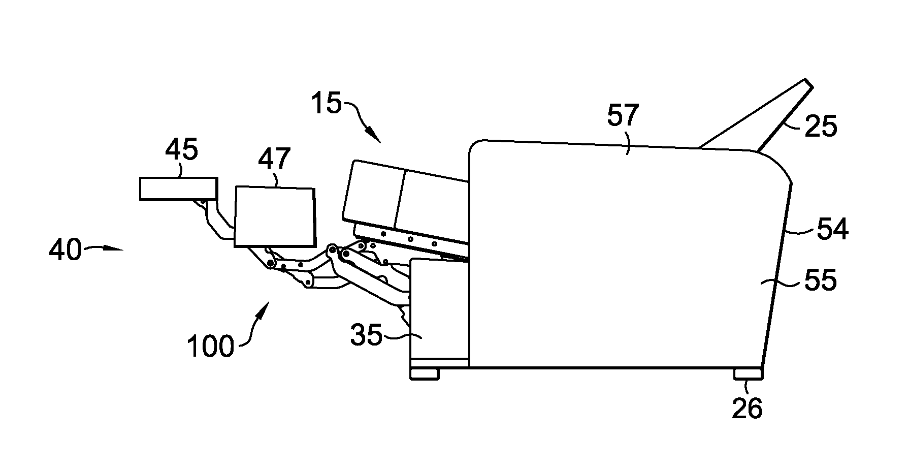
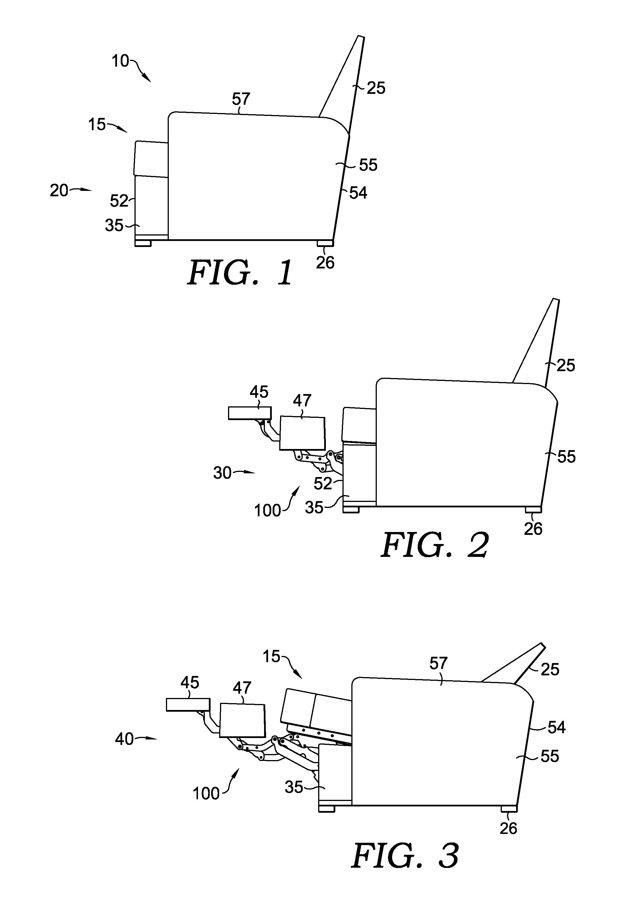
[0025]FIGS. 1-3 illustrate a seating unit 10. Seating unit 10 has a seat 15, a backrest 25, legs 26, a linkage mechanism 100, a first foot-support ottoman 45, a second foot-support ottoman 47, and a pair of opposed arms 55. A third foot-support ottoman (not shown) may be provided in some embodiments and may be installed to components of a flipper assembly (discussed below) that is selectively assembled in front of the footrest assembly. Opposed arms 55 are laterally spaced and have an arm-support surface 57 that is substantially horizontal. The opposed arms 55 are supported by the legs 26, which raise it above an underlying surface (not shown).

[0026]In addition, with respect to a frame-within-a-frame style chair, the opposed arms 55 are interconnected to the seat 15 via the linkage mechanism 100 that is generally disposed between the opposed arms (i.e., substantially above a lower edge of the opposed arms). In this embodiment, the seat 15 is moveable between the opposed arms 55 duri...


PUM


Abstract

Provided is a linkage mechanism for a recliner that includes a seat rail, an arm mounting plate that is vertically supported by one or more legs, a footrest assembly adapted to extend ottoman(s) when the recliner is adjusted from a closed to an extended position, and a roller link that translates forward when the recliner is adjusted from the extended position to a reclined position. The arm mounting plate includes a forward guide slot and a rearward guide slot having respective tracks installed thereto. The roller link includes a forward roller and a rearward roller that are rotatably coupled thereto. Further, the forward and rearward rollers are moveably engaged to the tracks of the forward and rearward guide slots, respectively, facilitating the forward translation of the roller link. A pair of substantially parallel-spaced TV links act in cooperation to pivotably couple the roller link to the arm mounting plate.

Description

CROSS-REFERENCE TO RELATED APPLICATIONS[0001]This application claims the benefit of U.S. Provisional Application No. 61 / 489,515, filed May 24, 2011, entitled “Enhanced Compatibility for a Linkage Mechanism,” herein incorporated by reference.BACKGROUND OF THE INVENTION[0002]The present invention relates broadly to motion upholstery furniture designed to support a user's body in an essentially seated disposition. Motion upholstery furniture includes recliners, incliners, sofas, love seats, sectionals, theater seating, traditional chairs, and chairs with a moveable seat portion, such furniture pieces being referred to herein generally as “seating units.” More particularly, the present invention relates to an improved linkage mechanism developed to accommodate a wide variety of styling for a seating unit (e.g., high-leg chairs), which is otherwise limited by the configurations of linkage mechanisms in the field.[0003]Reclining seating units exist that allow a user to forwardly extend a ...

Claims


Application Information

Patent Timeline
IPC IPC(8): A47C1/035G05G11/00
CPCA47C1/0355Y10T74/20207A47C1/0352
Inventor CRUM, MICHAEL
Owner L & P PROPERTY MANAGEMENT CO
Why Eureka
Try Eureka