

Gas tube structure
a technology of gas tube and pipe body, applied in the direction of pipe joints, flexible pipes, adjustable joints, etc., can solve the problems of increased cost, increased manpower, and easy deformation of pipe joints, so as to achieve stable connection, and avoid deformation or loosening
- Summary
- Abstract
- Description
- Claims
- Application Information
AI Technical Summary
Benefits of technology
Problems solved by technology
Method used
Image

Examples
Embodiment Construction
[0016]Embodiments of the present invention will now be described, by way of example only, with reference to the accompanying drawings.
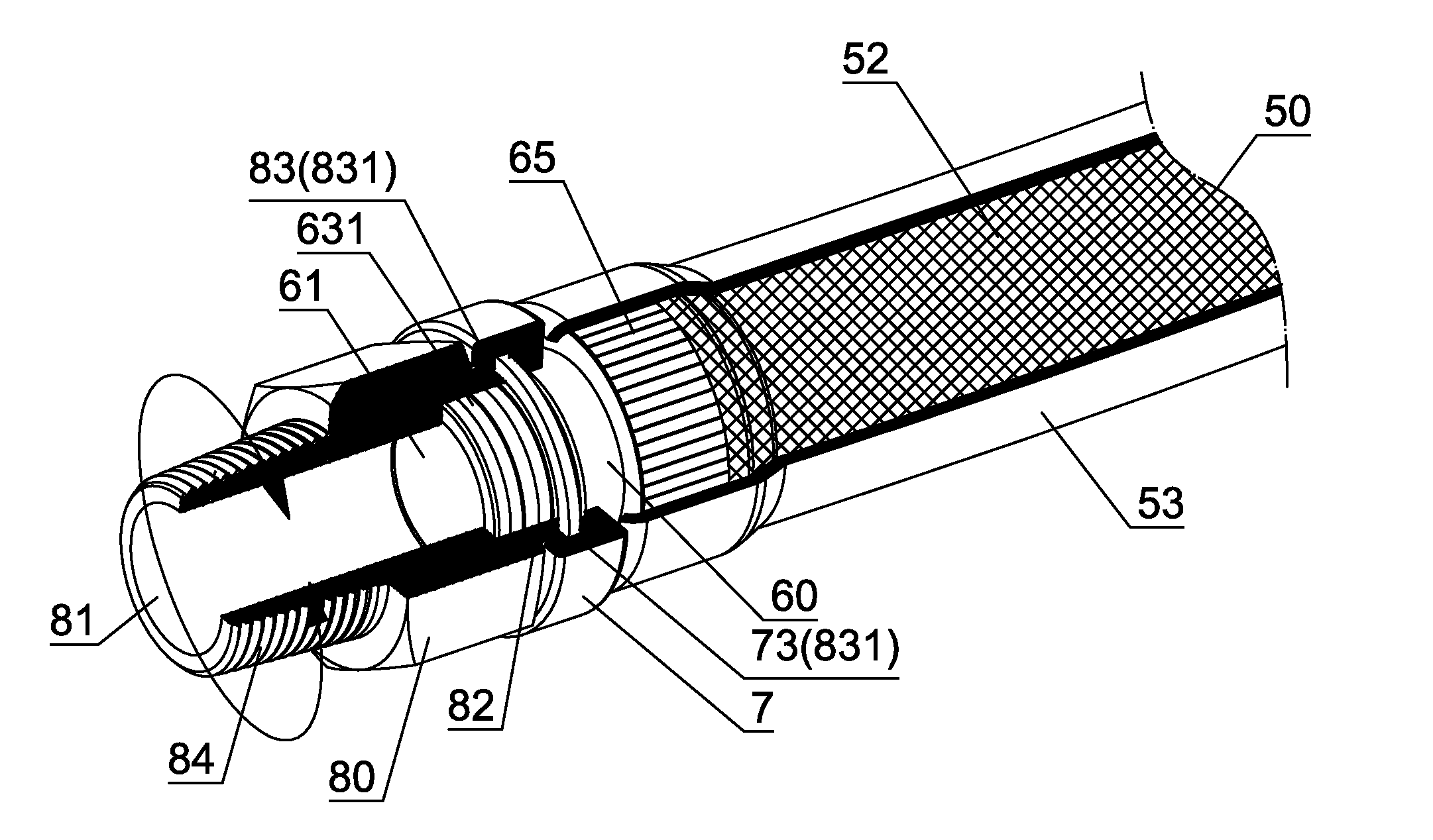
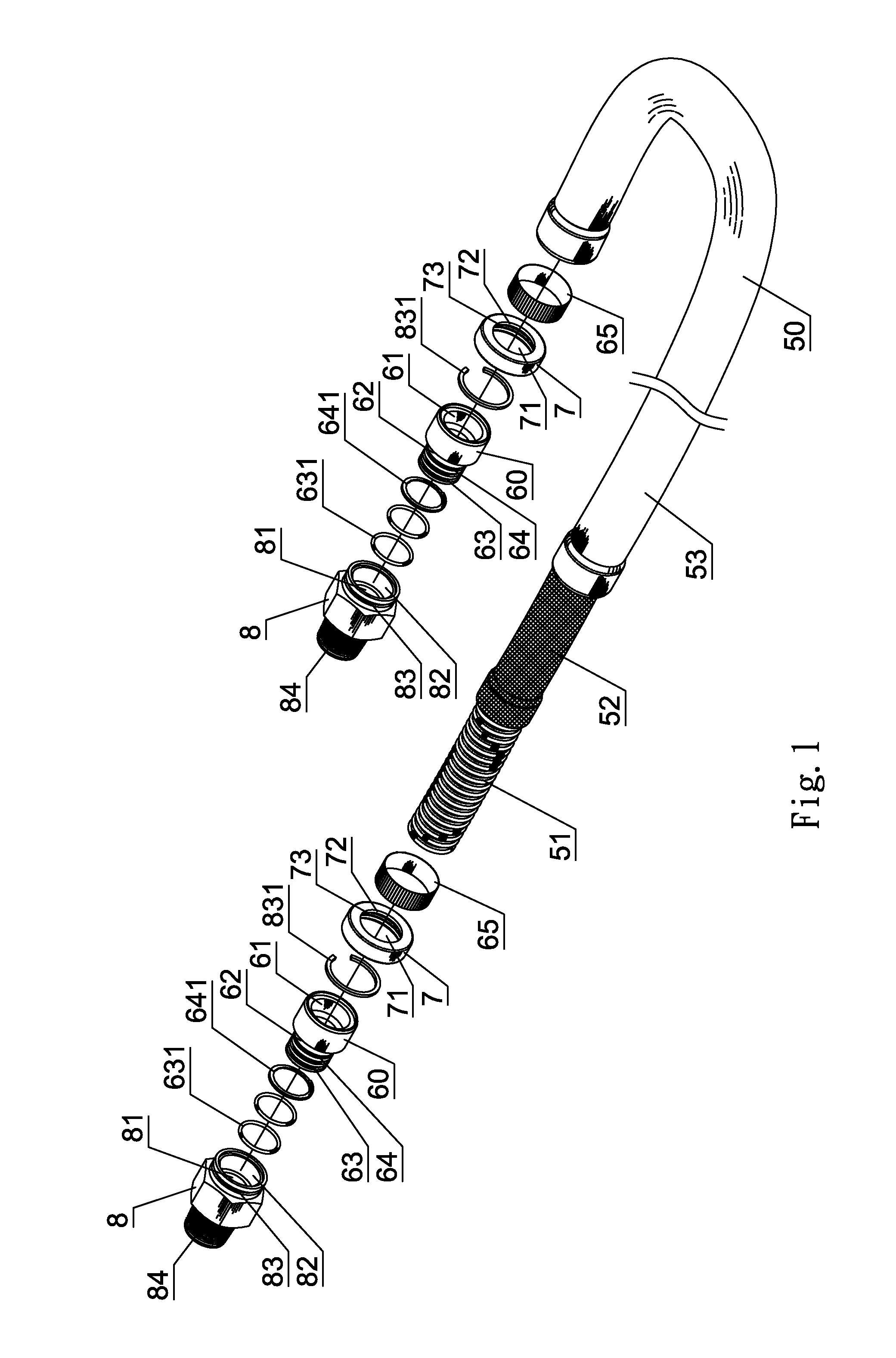
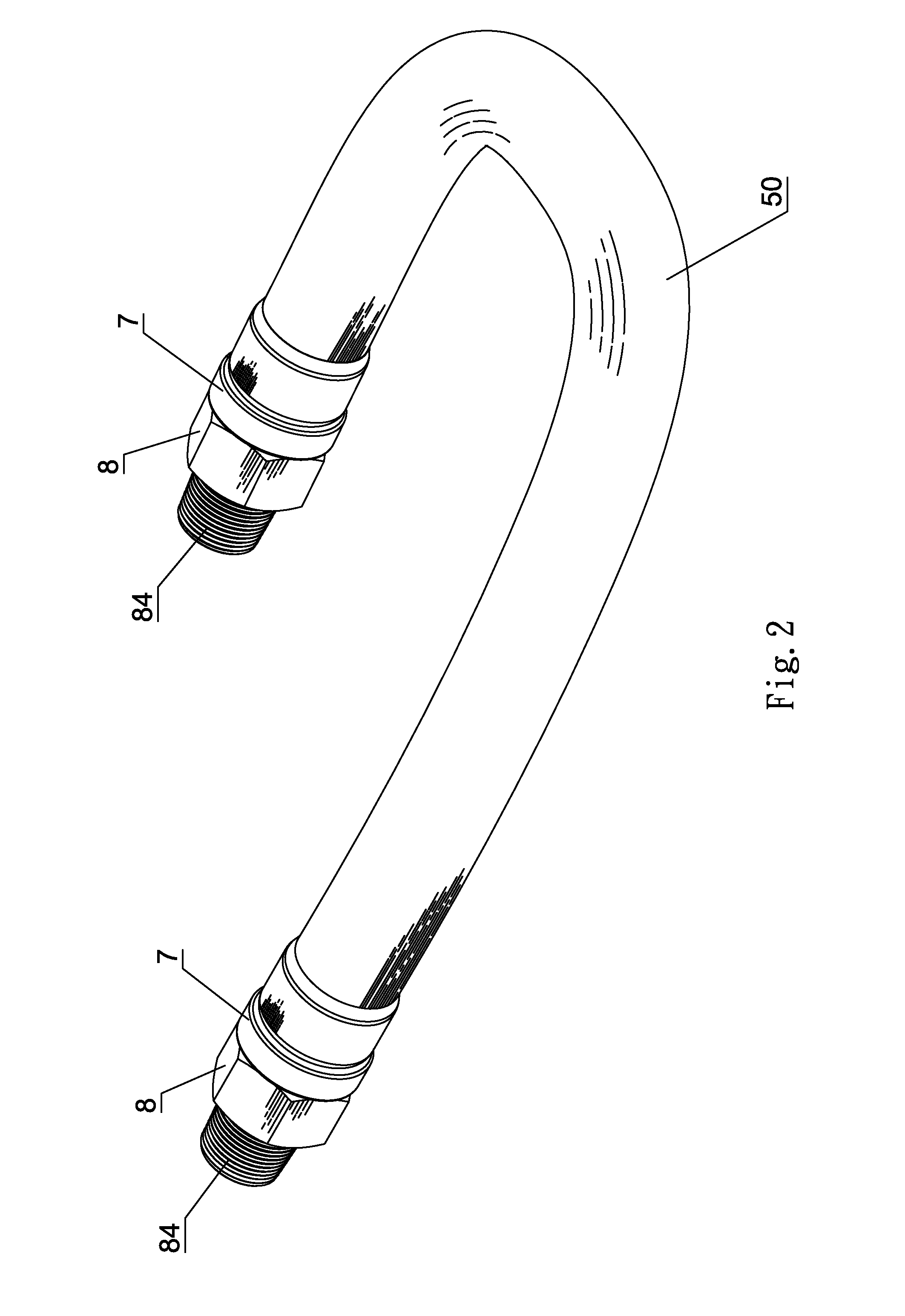
[0017]As shown in FIG. 1 through FIG. 3, the end of a flexible tube 50 is connected with a fixed connector 60. A sleeve 70 is fitted on the fixed connector 60. The fixed connector 60 and the sleeve 70 are connected to a movable connector 80. The flexible tube 50 includes a metallic tube layer 51, a metallic net layer 52 and a plastic tube layer 53 which are stacked from inside to outside in sequence. The fixed connector 60 is made of metal. The fixed connector 60 has a central through hole 61. The inner end of the fixed connector 60 is welded to the end of the metallic tube layer 51 to form a weld point A. A fastening ring 65 is connected with the metallic net layer 52 and fitted on the inner end of the fixed connector 60. The plastic tube layer 53 covers the fastening ring 65 to be one-piece. The fixed connector 60 has a connection section 62 extendi...
PUM
 Abstract
Description
Claims
Application Information