

Conveyance seat
- Summary
- Abstract
- Description
- Claims
- Application Information
AI Technical Summary
Benefits of technology
Problems solved by technology
Method used
Image


Examples
Embodiment Construction
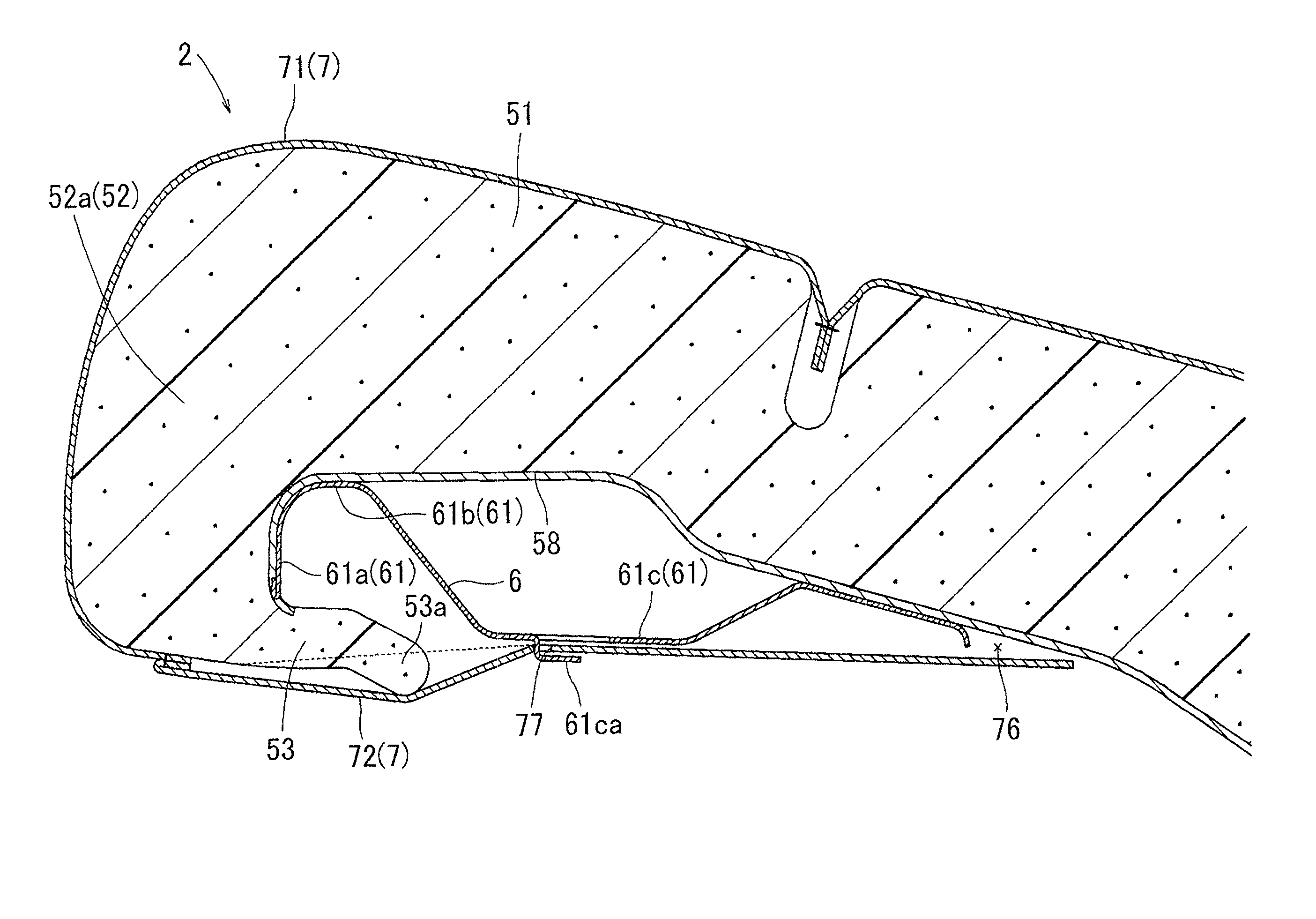
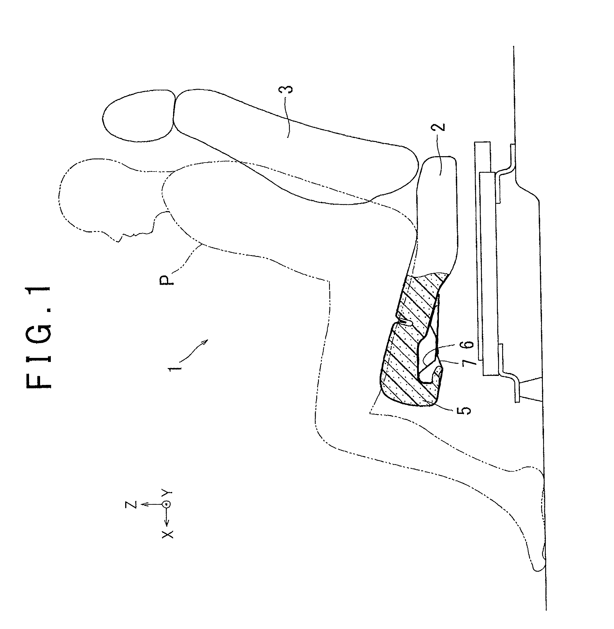
[0022]Hereinafter, example embodiments of the invention will be described with reference to the drawings when appropriate. Regarding directions such as a front-rear (longitudinal) direction, an up-down (vertical) direction, and a left-right (lateral) direction in this specification, X is designated as the forward direction, Y is designated as the left direction, and Z is designated as the upward direction, in FIG. 1. For example, normally the side that is in the field of view when an occupant P is seated is forward, and the side behind the head, which is not in the field of view, is rearward. The left-hand side of the occupant P in FIG. 1 is the left direction. A conveyance seat 1 in this example embodiment is a vehicle seat. The conveyance seat 1. in this example embodiment includes a seat cushion 2 that has a supporting surface that opposes mainly the thighs of the occupant P, and a seatback 3 that has a supporting surface that opposes mainly the back of the occupant P. Also, with...
PUM
 Abstract
Description
Claims
Application Information