Vehicle

a technology of turn shaft and steering angle, which is applied in the field of vehicles, can solve the problems of large space accommodating the respective turn shaft members and the movable range of components to be connected to the respective turnable members, and achieve the effects of improving the riding comfort level of the vehicle, reducing or preventing the enlargement of the movable range, and large steering angl

Active Publication Date: 2015-07-30
YAMAHA MOTOR CO LTD
View PDF14 Cites 17 Cited by
  • Summary
  • Abstract
  • Description
  • Claims
  • Application Information

AI Technical Summary

Benefits of technology

[0017]In the above-described vehicle, during steering, the first front wheel and the second front wheel are set to postures in which the Ackermann geometry is easily established. Therefore, even if a steering angle is large, the turning radius of the first front wheel is close to that of the second front wheel. For this reason, the first front wheel and the second front wheel are turned smoothly about their respective axles. As a result, the riding comfort level of the vehicle is improved.
[0018]Preferred embodiments of the present invention provide a vehicle that reduces or prevents enlargement of the movable ranges of the members that transmit a steering force while also providing a large steering angle.

Problems solved by technology

However, with this configuration, it is difficult to increase the steering angle of the vehicle because the turning ranges of the joint members are limited.
However, in such a configuration in which the turn shaft members are individually provided, the space accommodating the respective turn shaft members and the movable ranges of the components to be connected to the respective turnable members become large.

Method used


Image

  • Vehicle
  • Vehicle
  • Vehicle

Examples


first preferred embodiment

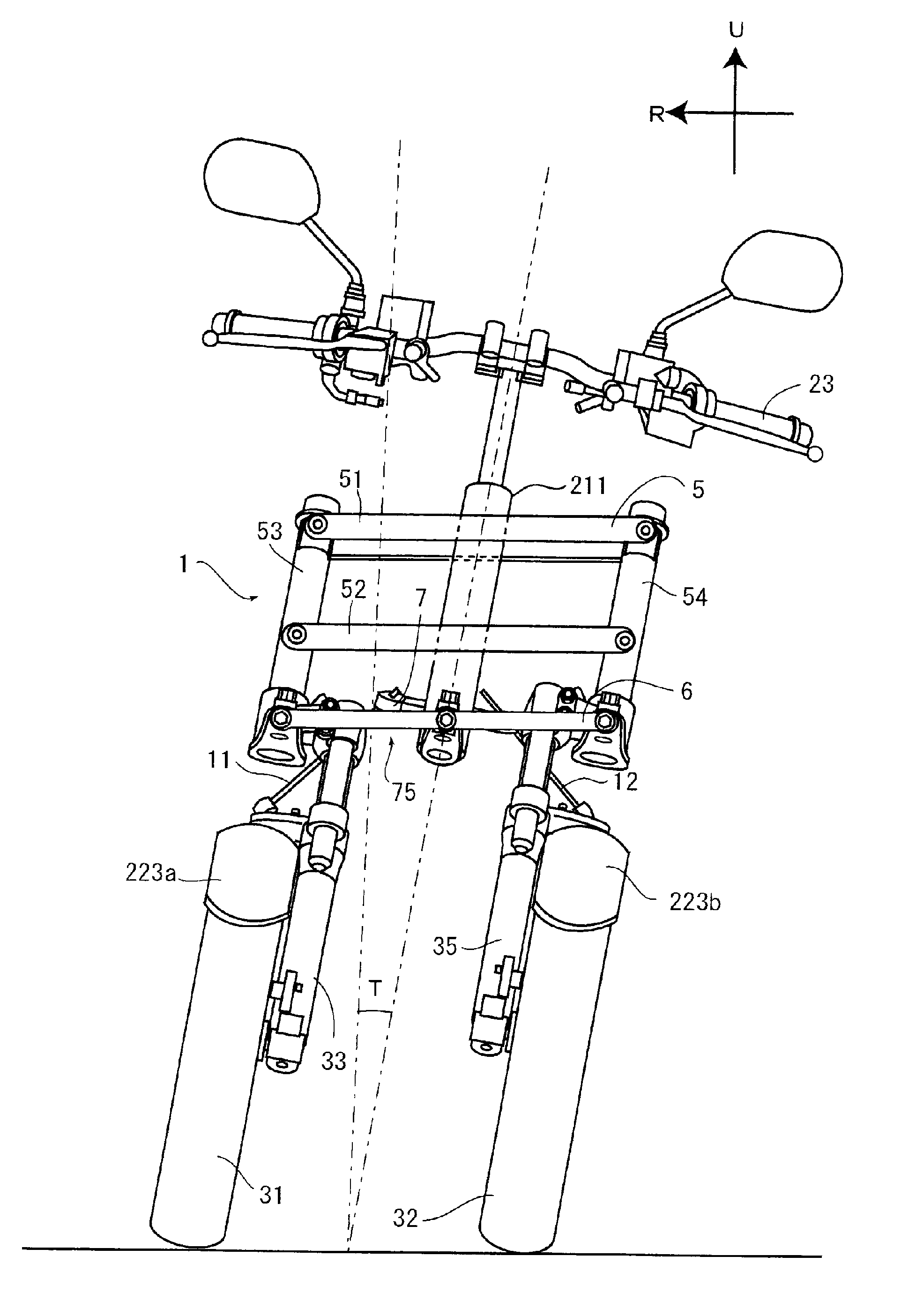
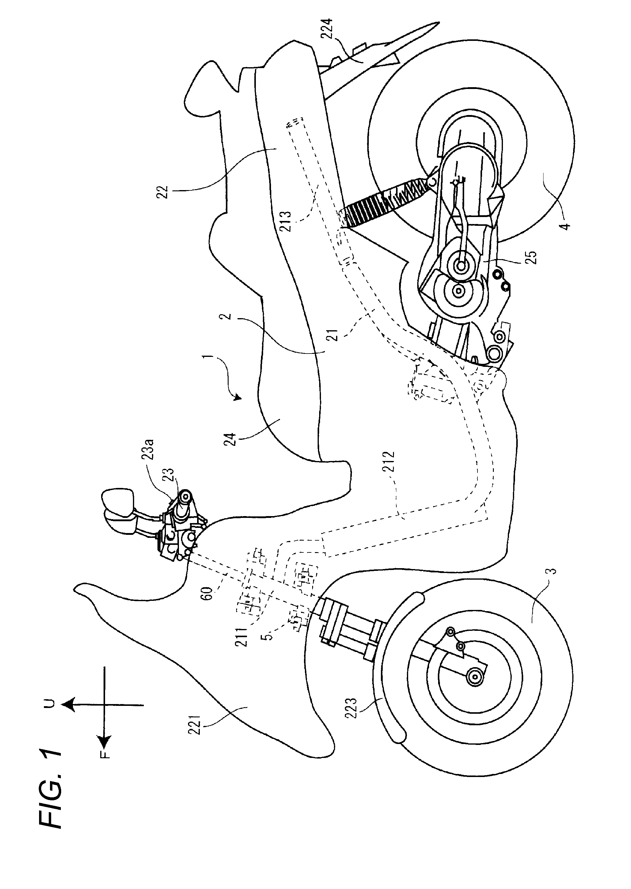
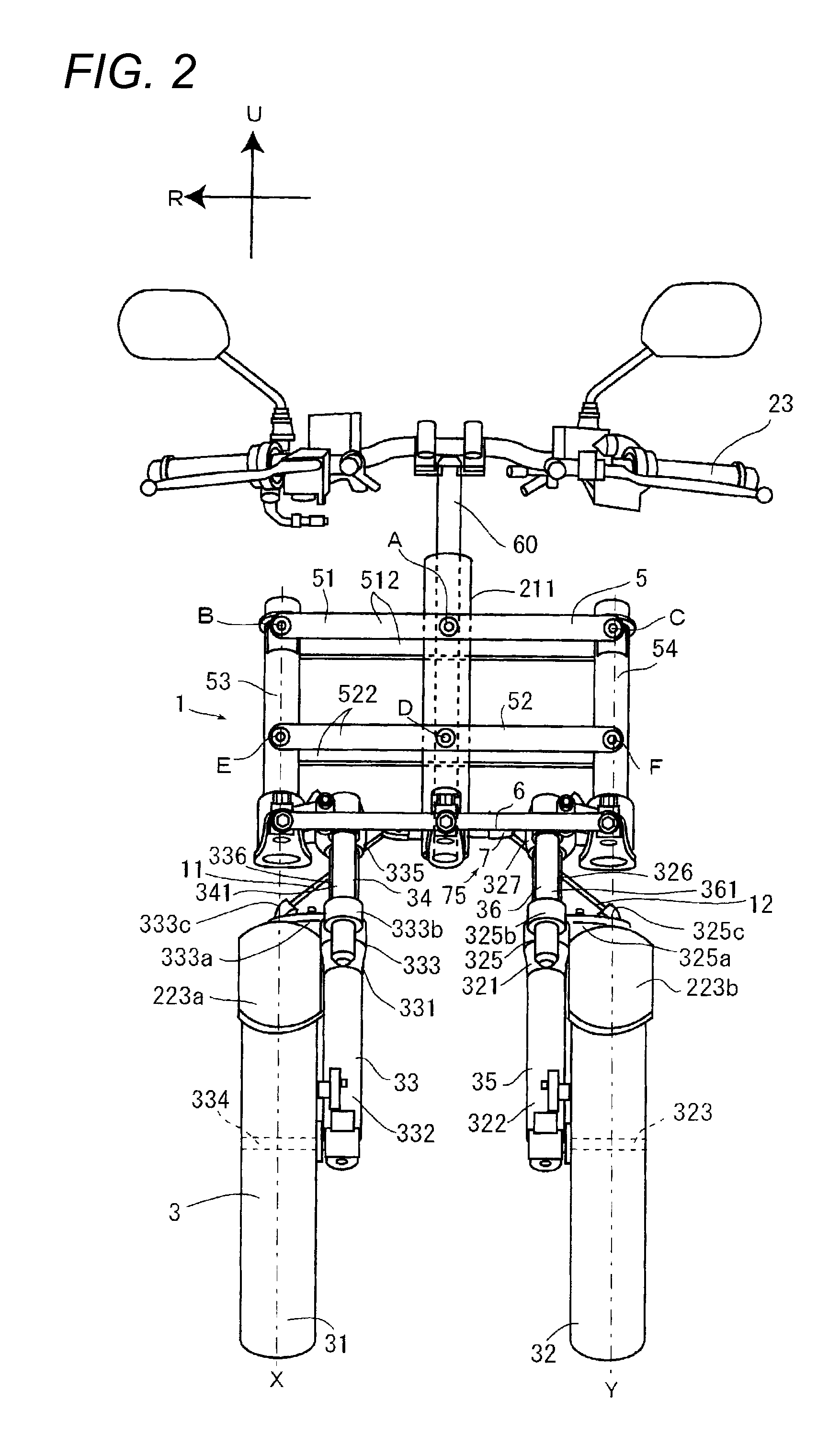
[0042]A three-wheel vehicle 1, which is one example of a vehicle according to a preferred embodiment of the present invention, will be described below referring to FIGS. 1 to 10. In the drawings, the same or corresponding components will be designated by the same numerals and their explanations will not be repeated. In the following descriptions, an arrow F in the drawings indicates the frontward direction of the three-wheel vehicle 1. An arrow R in the drawings indicates the rightward direction of the three-wheel vehicle 1. An arrow L in the drawings indicates the leftward direction of the three-wheel vehicle 1. An arrow U in the drawings indicates the upward direction of the three-wheel vehicle 1. Outward in the vehicle width direction denotes an outward direction from the center in the vehicle width direction. In other words, outward in the vehicle width direction denotes a direction from the center in the vehicle width direction to the leftward or rightward direction. The expres...

second preferred embodiment

[0110]A vehicle according to a second preferred embodiment of the present invention will be described below referring to FIGS. 11 to 21.

[0111]In this preferred embodiment, as one example of a vehicle, a straddle type three-wheel vehicle (hereafter referred to as a vehicle) with two front wheels and one rear wheel, will be exemplified.

[0112]FIG. 11 is an overall side view showing the vehicle as viewed from the left side of the vehicle. In the following descriptions, an arrow F in the drawings indicates the frontward direction of the vehicle and an arrow B indicates the rearward direction of the vehicle. An arrow U indicates the upward direction of the vehicle and an arrow D indicates the downward direction of the vehicle. When the front-rear direction and the left-right direction are indicated in the descriptions, the directions denote the front-rear direction and the left-right direction as viewed from the driver on the vehicle. The center in the vehicle width direction denotes the ...


PUM


Abstract

A vehicle includes a center transmission plate, a first center turnable portion configured to turn about a first center turning axis extending in an up-down direction, a second center turnable portion configured to turn about a second center turning axis extending in a front-rear direction, a left transmission plate, a first left turnable portion configured to turn about a first left turning axis extending in the up-down direction, a second left turnable portion configured to turn about a second left turning axis extending in the front-rear direction, a right transmission plate, a first right turnable portion configured to turn about a first right turning axis extending in the up-down direction, and a second right turnable portion configured to turn about a second right turning axis extending in the front-rear direction. A tie rod is supported on the second center turnable portion, the second left turnable portion, and the second right turnable portion.

Description

BACKGROUND OF THE INVENTION[0001]1. Field of the Invention[0002]The present invention relates to a vehicle including a tiltable vehicle body frame and two front wheels.[0003]2. Description of the Related Art[0004]There has been disclosed a vehicle including a tiltable vehicle body frame, two front wheels, and a steering mechanism to transmit a steering force input to turn a steering shaft to a first front wheel and a second front wheel (see International Publication No. WO 2012 / 007819).[0005]In the vehicle disclosed in International Publication No. WO 2012 / 007819, joint members are turnable in two axial directions to perform a turning operation to transmit a steering force to the two front wheels and to perform a turning operation to allow the two front wheels to move in the up-down direction. However, with this configuration, it is difficult to increase the steering angle of the vehicle because the turning ranges of the joint members are limited.[0006]Hence, it is conceivable to in...

Claims


Application Information

Patent Timeline
Patent Type & Authority Applications(United States)
IPC IPC(8): B62K5/08B62K5/027B62K5/05B62K5/10
CPCB62K5/08B62K5/10B62K2005/001B62K5/05B62K5/027B60G3/01B60G2200/44B60G2204/422B60G2204/8302B60G2300/122B60G2300/45B62K21/18
Inventor IIZUKA, TOSHIOHIRAYAMA, YOSUKEKUBO, YUTAKAWATANABE, TAKAHIROMIYAMOTO, NOBORUSASAKI, KAORUOGAWA, HIROKATSU
Owner YAMAHA MOTOR CO LTD
Why Eureka
Try Eureka