Cleaning devices with selectively flexible or rigid handles

a technology of cleaning devices and handles, applied in the field of cleaning devices, can solve the problems of inflexibility and flexibility of prior art cleaning devices, and achieve the effect of applying different levels of cleaning for

a technology of cleaning devices and handles, applied in the field of cleaning devices, can solve the problems of inflexibility and flexibility of prior art cleaning devices, and achieve the effect of applying different levels of cleaning for

US20160029859A1Active Publication Date: 2016-02-04UNGER MARKETING INT

Image

  • Cleaning devices with selectively flexible or rigid handles
  • Cleaning devices with selectively flexible or rigid handles
  • Cleaning devices with selectively flexible or rigid handles

Examples


Embodiment Construction

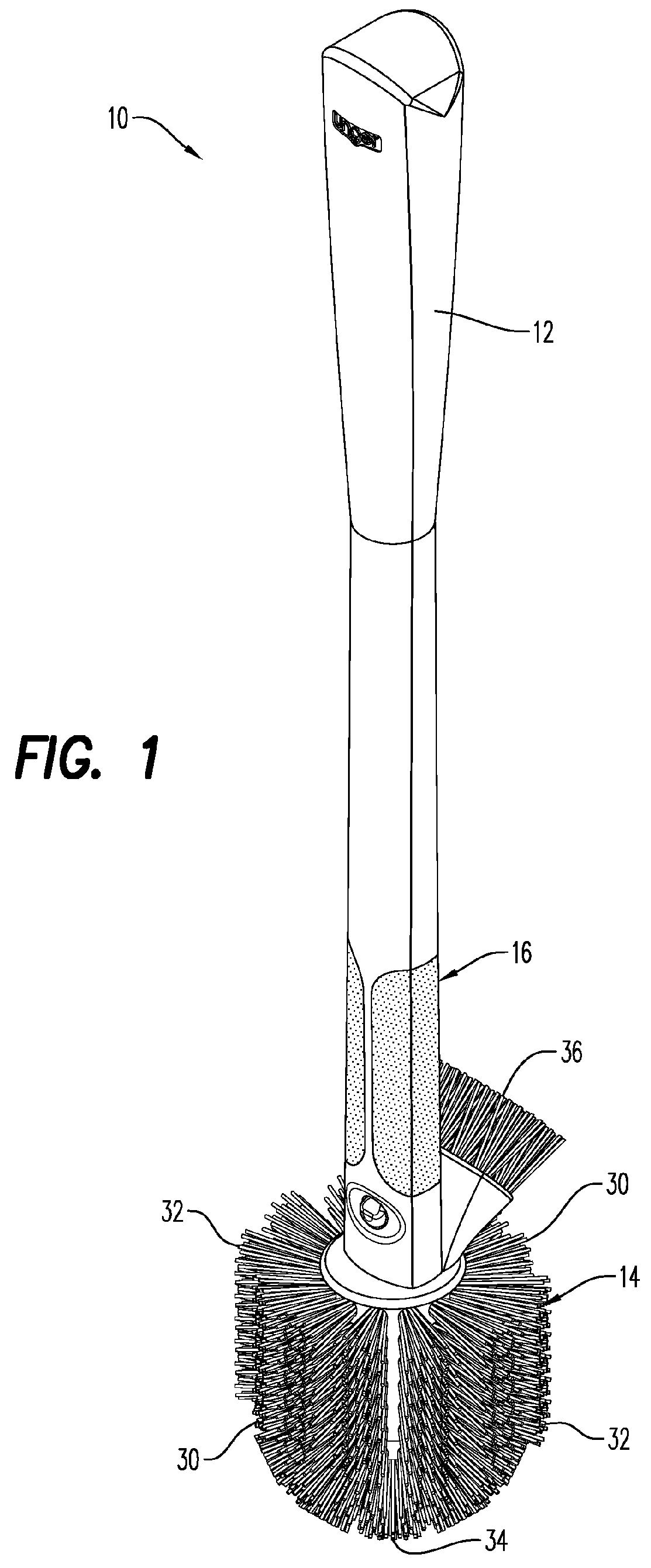
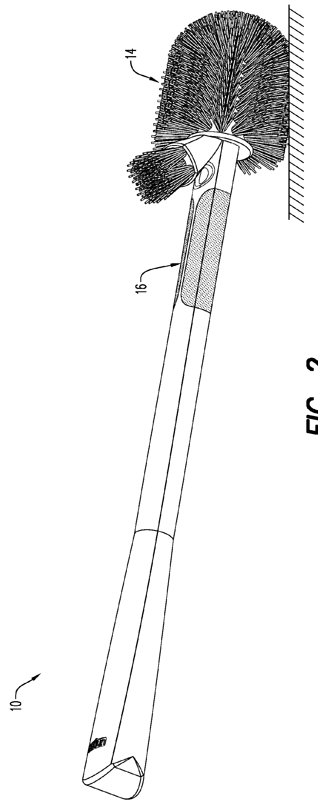
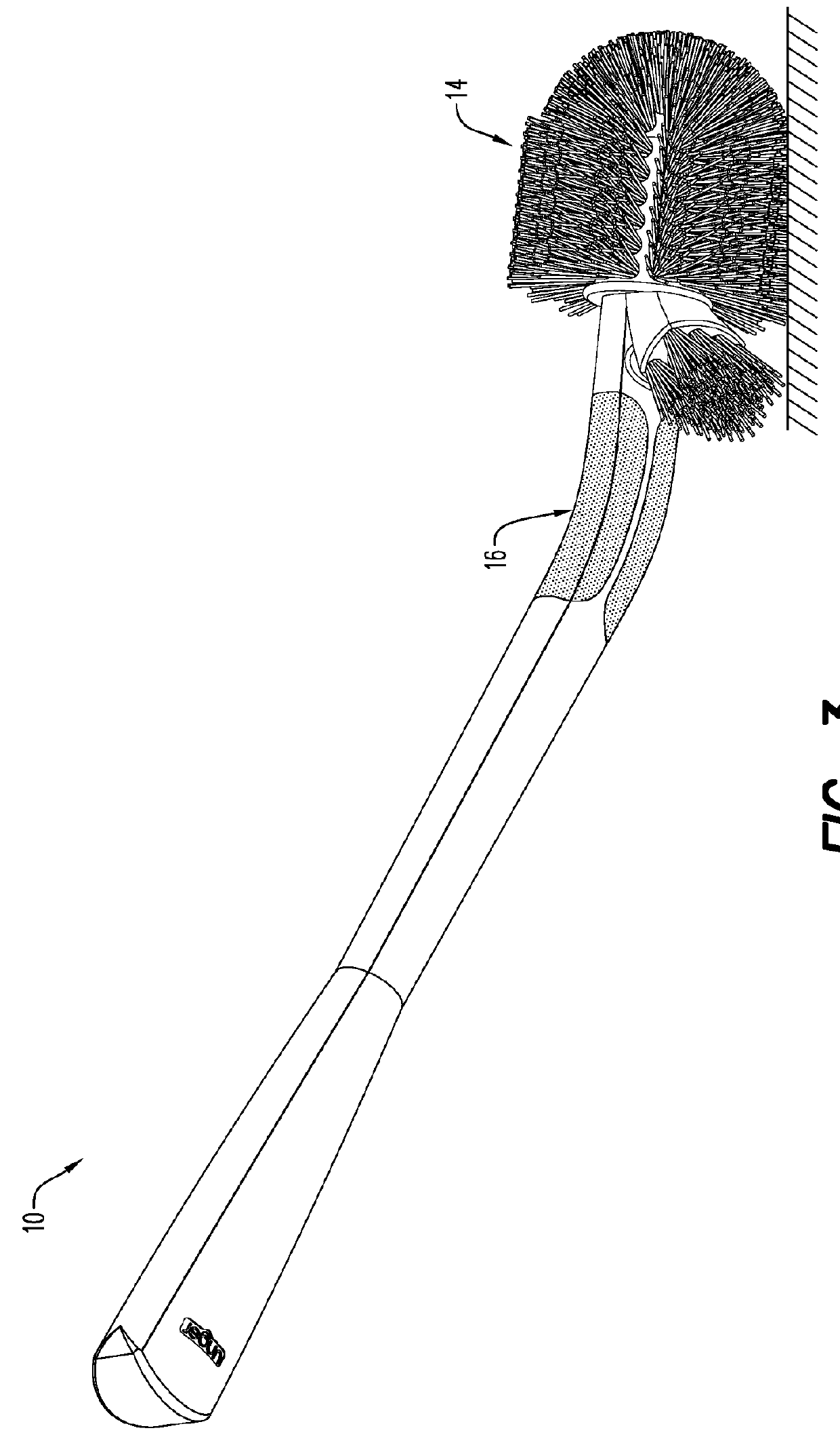
[0037]Referring to the drawings and in particular to FIGS. 1 through 3, an exemplary embodiment of a cleaning device is shown and is generally referred to by reference numeral 10. Cleaning device 10 includes a handle 12 and a cleaning head 14. Advantageously, handle 12 includes a zone 16 that is rigid or inflexible in a first orientation (FIG. 2), but is resiliently flexible in a second orientation (FIG. 3).

[0038]Cleaning device 10 is shown by way of example only as a toilet brush. Of course, it is contemplated by the present disclosure for cleaning device 10 to include any type of cleaning device having a handle 12 and a cleaning head 14 such as, but not limited to, dusting devices, wiping devices, brushing devices, mopping devices, and others. For example, cleaning device 10 can be a wiping device for cleaning windows, mirrors, or other surfaces, a brushing device for cleaning surfaces that have difficult to remove debris and / or difficult to reach locations (e.g., toilet trap), a ...


PUM

PropertyMeasurementUnit
forcesaaaaaaaaaa
cleaning forceaaaaaaaaaa
thicknessaaaaaaaaaa

Abstract

A cleaning device is provided that has a handle configured to provide flexion in a first orientation but to provide rigidity in a second orientation. In this manner, the user can use the handle in the first orientation to allow the cleaning device to flex into hard to reach places and can use the same handle in the second orientation to apply differing levels of cleaning force.

Description

CROSS REFERENCE TO RELATED APPLICATIONS[0001]This application claims the benefit of U.S. Provisional Application Ser. No. 62 / 022,852 filed on Jul. 10, 2014, is a continuation of U.S. Design Application No. 29 / 496,191 filed on Jul. 10, 2014, and is a continuation of U.S. Design Application No. 29 / 511,377 filed on Dec. 10, 2014, the entire contents of all of which are incorporated by reference herein.BACKGROUND[0002]1. Field of the Disclosure[0003]The present disclosure is related to cleaning devices. More particularly, the present disclosure is related to cleaning devices with handles that are selectively flexible or rigid based on their orientation.[0004]2. Description of Related Art[0005]Cleaning devices that have handles are known. These cleaning devices can include, but are not limited to, dusting devices, wiping devices, brushing devices, mopping devices, and others.[0006]In some cleaning applications, it is desired for the handle to resiliently flex or bend (hereinafter “flex”)...

Claims


Application Information

Patent Timeline
04 Feb 2016
Publication
US20160029859A1
IPC
A46B5/02; A47K11/10
CPC
A46B5/02; A47K11/10; A46B5/0037; A46B5/0095; A46B9/02; A46B2200/304; A46B5/0062; A46B5/0066
Inventors
HARRINGTON, WILLIAM; TRIUNFO, JOHN A.