

Liquid ejecting apparatus
a technology of liquid ejecting apparatus and liquid, which is applied in the direction of printing, etc., can solve the problems of taking a lot of time and effort to empty or replace the tank, and achieve the effect of simplifying the apparatus
- Summary
- Abstract
- Description
- Claims
- Application Information
AI Technical Summary
Benefits of technology
Problems solved by technology
Method used
Image

Examples
first embodiment
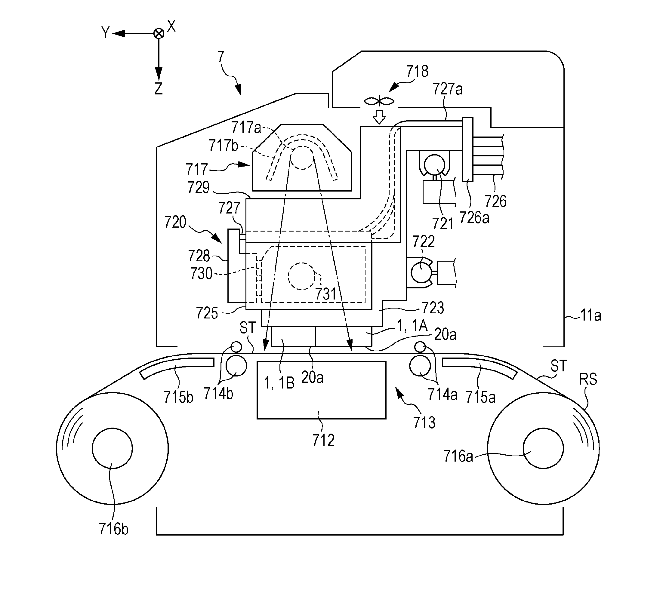
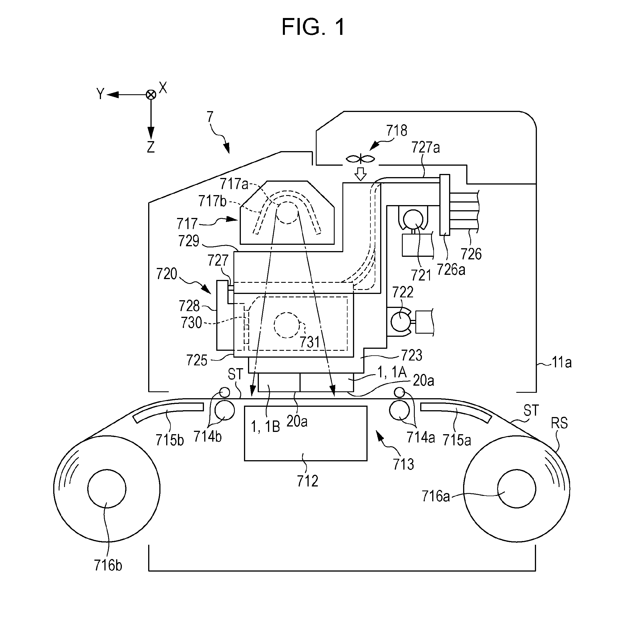
[0058]As shown in FIG. 1, the liquid ejecting apparatus 7 is provided with a transport unit 713 with which the sheet-like medium ST supported on the support stand 712 is transported in the transport direction Y along the surface of the support stand 712, a printing unit 720 that performed printing while ejecting ink as an example of the first liquid to the transported medium ST, and a heating unit 717 and a blower 718 for causing the ink landed on the medium ST to dry.
[0059]The support stand 712, the transport unit 713, the heating unit 717, the blower 718, and the printing unit 720 are assembled in a printer main body 11a configured by a housing, a frame and the like. In the printer main body 11a, the support stand 712 extends in the width direction (in FIG. 1, direction orthogonal to the paper surface) of the medium ST.
[0060]The transport unit 713 is provided with a transport roller pair 714a and a transport roller pair 714b arranged on the upstream side and the downstream side of...
second embodiment
[0228]Next, the second embodiment of the liquid ejecting apparatus will be described with reference to the drawings.
[0229]Since configurations to which the same reference numerals at the first embodiment are applied in the second embodiments include the same configurations as the first embodiment, description thereof will not be provided, and description below will be provided focusing on the points of difference from the first embodiment.
[0230]As shown in FIG. 16, the fluid ejecting device 775D provided in the liquid ejecting apparatus of the embodiment is configured so the direction in which the fluid ejecting nozzle 778 ejects the fluid is changeable. The position of the fluid ejecting nozzle 778 when ejecting the fluid in the first ejection direction S1 substantially orthogonal to the opening surface (liquid ejecting surface 20a) in which the nozzle 21 opens is referred to as the first position P1. The position of the fluid ejecting nozzle 778 when ejecting the fluid in the seco...
third embodiment
[0318]Next, the third embodiment of the liquid ejecting apparatus will be described with reference to the drawings.
[0319]Since configurations to which the same reference numerals at the first embodiment are applied in the third embodiments include the same configurations as the first embodiment, description thereof will not be provided, and description below will be provided focusing on the points of difference from the first embodiment.
[0320]As shown in FIG. 24, the liquid ejecting apparatus 7 of the embodiment includes a leg portion 850 which supports a printer main body 11a. In addition, in the liquid ejecting apparatus 7, the guide plate 715a and the guide plate 715b which are included in the transport unit 713 configure a support precursor part 851 which is provided in a state where the end portion in a discharging direction Y is protruded from the printer main body 11a. The inside of the support precursor part 851 is formed in a hollow box shape.
[0321]In a case where the inter...
PUM
 Abstract
Description
Claims
Application Information