Roof airbag apparatus

a technology for airbags and hoods, which is applied in the direction of pedestrian/occupant safety arrangements, vehicular safety arrangments, vehicle components, etc., can solve the problems of reducing the deployment speed, affecting the safety of passengers, and the occupants' safety, so as to prevent an injury or separation of passengers

Active Publication Date: 2018-06-14
HYUNDAI MOBIS CO LTD
View PDF3 Cites 13 Cited by
  • Summary
  • Abstract
  • Description
  • Claims
  • Application Information

AI Technical Summary

Benefits of technology

[0007]Embodiments of the present invention are directed to a roof airbag apparatus capable of preventing an injury or separation of a passenger, which may be caused by a damage of a panorama sunroof or the like, when a vehicle accident occurs.

Problems solved by technology

The conventional airbag apparatus has a problem in that an upper chamber part of the vehicle has not completely covered a panorama sunroof or the like and the deployed chamber part could not stably support a passenger when the chamber part is moved or separated.
Furthermore, when the chamber part is expanded, the frictional force between guide taps and a tether guide may be increased to lower the deployment speed, and the guide taps may be damaged.

Method used


Image

  • Roof airbag apparatus
  • Roof airbag apparatus
  • Roof airbag apparatus

Examples


Embodiment Construction

[0025]Embodiments of the invention will hereinafter be described in detail with reference to the accompanying drawings. It should be noted that the drawings are not to precise scale and may be exaggerated in thickness of lines or sizes of components for descriptive convenience and clarity only.

[0026]Furthermore, the terms as used herein are defined by taking functions of the invention into account and can be changed according to the custom or intention of users or operators. Therefore, definition of the terms should be made according to the overall disclosures set forth herein.

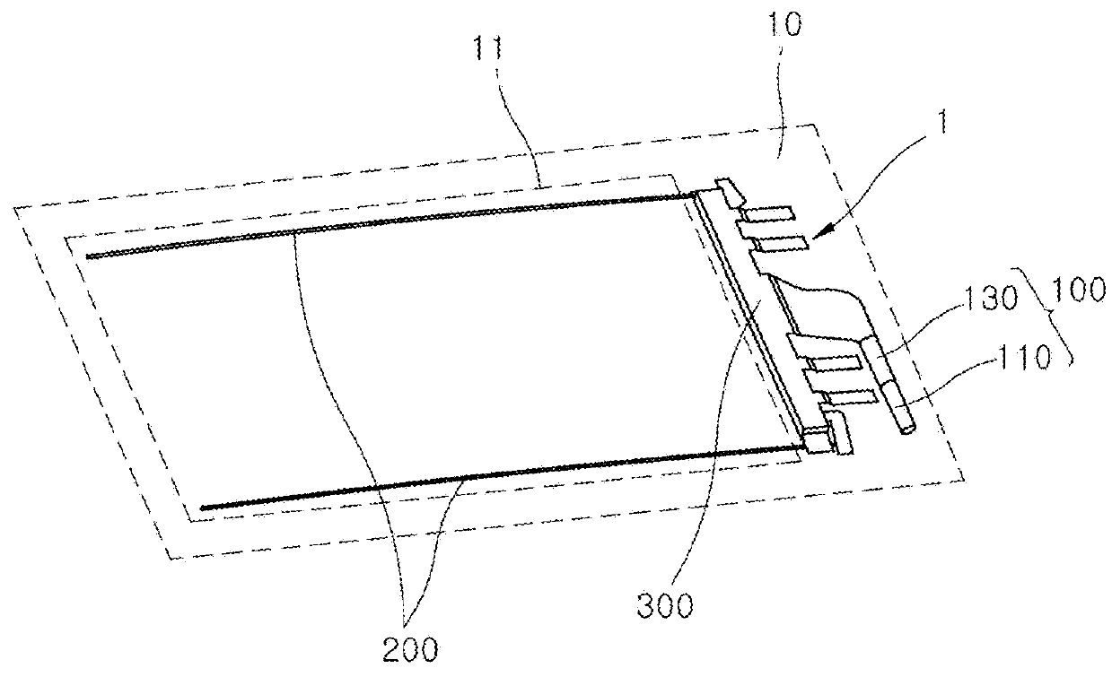
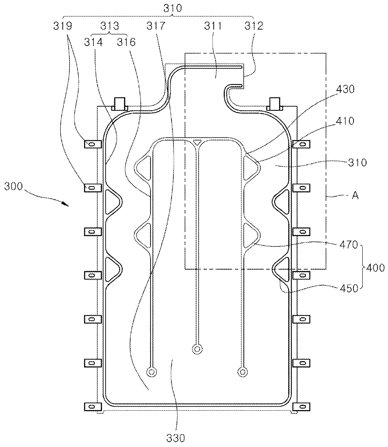
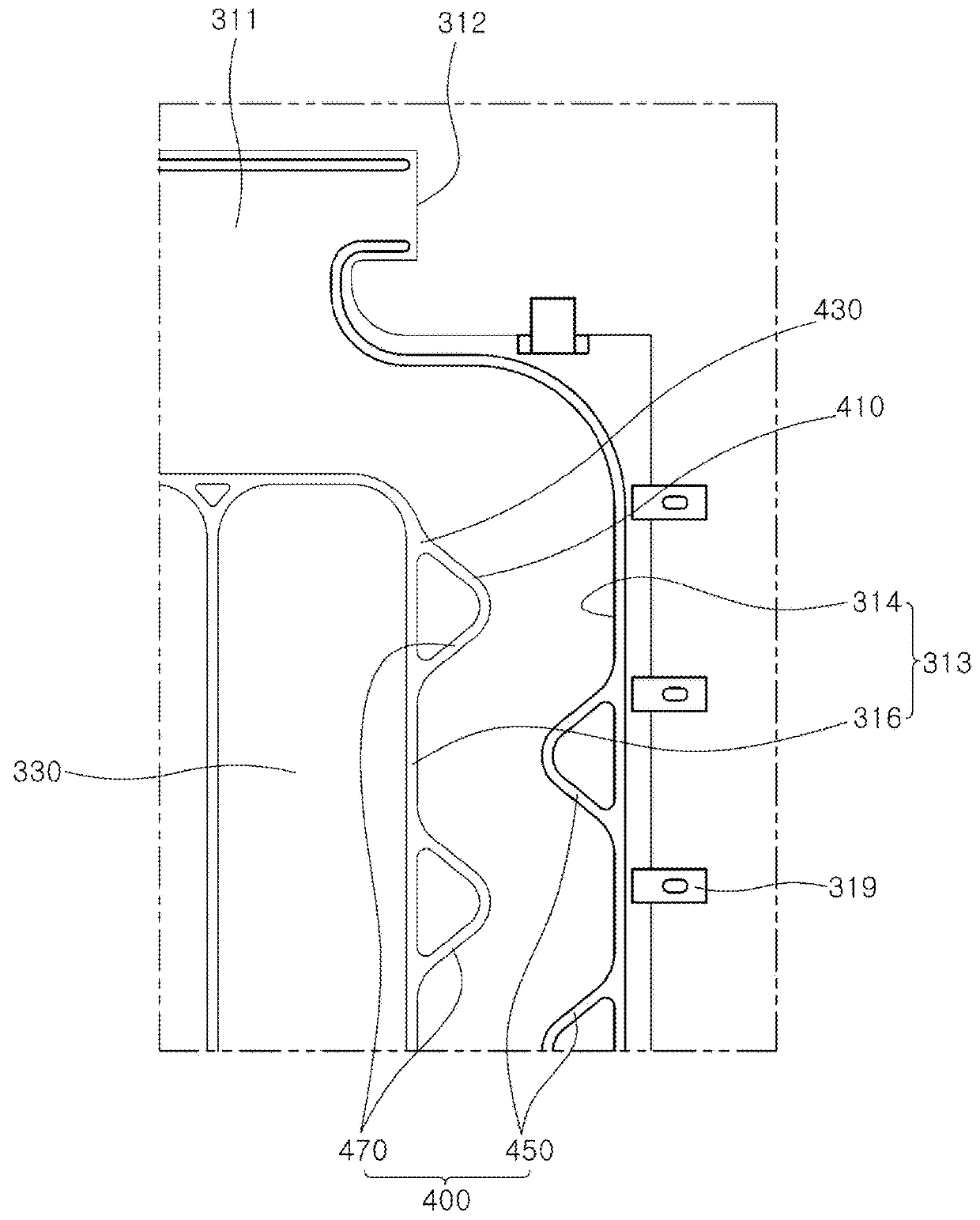
[0027]FIG. 1 is a perspective view illustrating that a chamber part of a roof airbag apparatus in accordance with an embodiment of the present invention is folded and installed in a vehicle, FIG. 2 is a plan view of the roof airbag apparatus in accordance with the embodiment of the present invention, and FIG. 3 illustrates a portion A of FIG. 2.

[0028]Referring to FIGS. 1 to 3, the roof airbag apparatus 1 in ac...


PUM


Abstract

A roof airbag apparatus may include: a gas injector configured to inject gas; a tether guide disposed along the longitudinal direction of a roof; a chamber part connected to the tether guide, and deployed by gas received from the gas injector; and a chamber moving part installed in the chamber part, and moving the chamber part while being pressed by the gas transferred to the chamber part.

Description

CROSS-REFERENCES TO RELATED APPLICATIONS[0001]The present application claims priority to Korean application number 10-2016-0168989, filed on Dec. 12, 2016, which is incorporated by reference in its entirety.BACKGROUND OF THE INVENTION[0002]The present invention relates to a roof airbag apparatus, and more particularly, to a roof airbag apparatus capable of preventing an injury or separation of a passenger when a vehicle accident occurs.[0003]In general, a vehicle includes an airbag apparatus installed to protect a passenger. The airbag apparatus may be installed at the front, both sides and top of the vehicle depending on the spec of the vehicle.[0004]A conventional airbag apparatus includes a gas injector and a chamber part. When a predetermined magnitude or more of external shock is applied to a vehicle, the gas injector generates gas and injects the generated gas into the chamber part to deploy the chamber part, thereby protecting the body of a passenger.[0005]The conventional ai...

Claims


Application Information

Patent Timeline
Patent Type & Authority Applications(United States)
IPC IPC(8): B60R21/233B60R21/2338
CPCB60R21/233B60R21/2338B60R2021/23192B60R2021/23316B60R21/213B60R21/264B60R21/268B60R2021/0018B60R21/214B60R21/231B60R2021/161B60R2021/23386
Inventor LEE, SEOK MINPARK, HAE KWONLEE, KYU SANGMIN, BYUNG HO
Owner HYUNDAI MOBIS CO LTD
Why Eureka
Try Eureka