Optical Zoom System And Method For Its Use

a technology of optical zoom and optical axis, which is applied in the field of optical axis zoom system, can solve the problems of difficult endoscopic imaging, difficult zooming and focusing, and the use of most conventional lens actuators with too much radial space, and achieve the effect of small form factor and easy manufacture and us

Active Publication Date: 2018-06-14
KARL STORZ IMAGING INC
View PDF1 Cites 1 Cited by
  • Summary
  • Abstract
  • Description
  • Claims
  • Application Information

AI Technical Summary

Benefits of technology

The invention aims to provide a small size optical zoom and focus system. By placing the zoom system on the side of a device that receives optical images, the light beam can be expanded before focusing and capturing. This expanded beam allows for the use of movable, solid lenses in a wider aperture area. The device incorporates this novel feature to expand the beam before one or more larger lens groups shape the light beam. This system is easier to manufacture, use, and cheaper with only one deformable lens.

Problems solved by technology

Endoscopic imaging is difficult due to limitations of form factor, propagation losses, and the wide range of distances at which objects are observed with an endoscope.
The small diameter of the light carrier and corresponding light beam also makes zooming and focusing particularly difficult.
Because of the small diameter, most conventional lens actuators require too much radial space to be used.
Both the methods of variable focus in Pauker, however, require complicated hydraulics, specialized fluids and sealed chambers which are difficult to manufacture and use.
However, the prior art devices use deformable lenses instead of moveable lenses due to the limitations of the form factor of an endoscope.
The listed prior art above describes these limitations as necessitating the replacement of the smaller moving lenses with liquid deformable lenses.
These liquid lenses have several disadvantages including the need for specialized actuators for displacing fluid, low durability and resilience, and higher optical imperfections like variable astigmatisms which cannot be corrected.
They are also difficult to manufacture and use.

Method used


Image

  • Optical Zoom System And Method For Its Use
  • Optical Zoom System And Method For Its Use
  • Optical Zoom System And Method For Its Use

Examples


Embodiment Construction

[0033]As used herein, first elements (e.g., sensors and lenses) that are “optically arranged” in relation to other elements, refers to the first elements' position along an common optical path that includes first and other elements. For example, a lens group optically arranged between an image sensor and an objective, means that the lens group occupies a portion of the optical path that light travels (e.g., from the objective to the image sensor) for capturing images or video. “Optical instruments” include instruments such as microscopes, exoscopes, borescopes, endoscopes, telescopes, video and / or still-image cameras, including optoelectronic implementations thereof. “Optical image” is an image formed by the light rays from a self-luminous or an illuminated object that traverse an optical system or element.

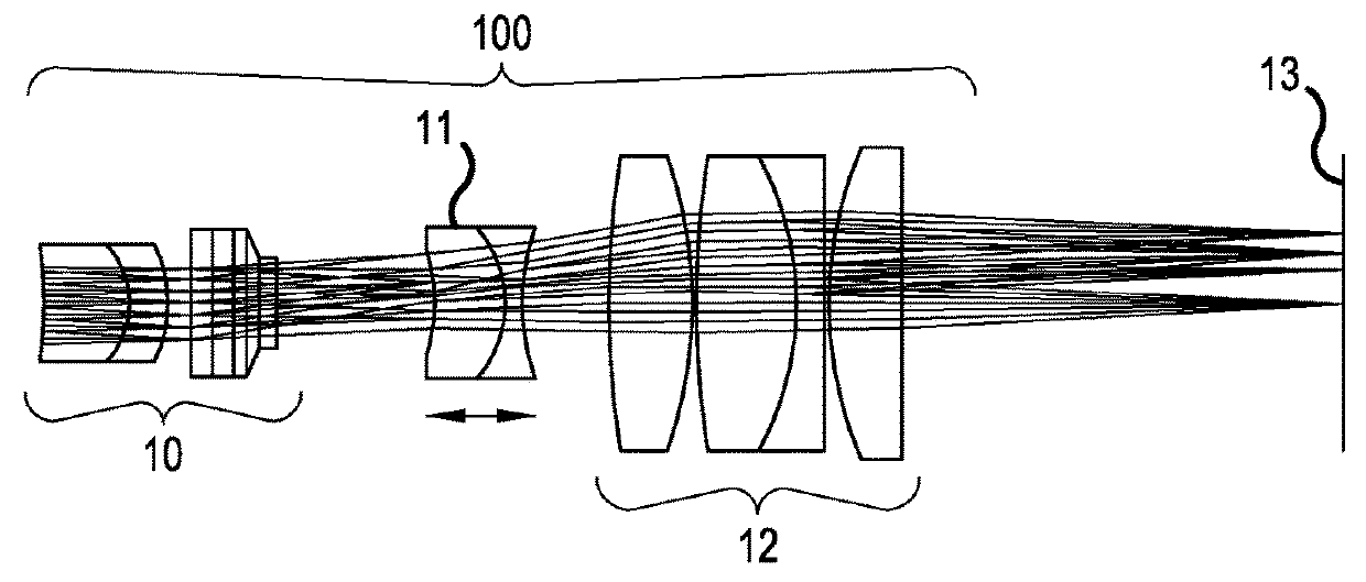
[0034]The optoelectronic device of FIG. 2 shows a zoom system 100, which includes a first positive, fixed lens group 10 with a deformable lens having variable curvature, a second ...


PUM


Abstract

A camera head is provided that includes a first lens group, including at least one deformable lens with variable curvature, a second lens group moveable relative to the first lens group, and an image sensor for capturing a light beam received from an endoscope, wherein the first lens group is fixed relative to the image sensor and the aperture of the first lens group is smaller than the aperture of the second lens group. A method is also provided for capturing of an image utilizing a zoom system including a variable power first lens group and a movable second lens group.

Description

CROSS-REFERENCE TO RELATED APPLICATIONS[0001]This application is a continuation of U.S. patent application Ser. No. 15 / 271,057, filed 20 Sep. 2016, and entitled “Optical Zoom System”, which is hereby incorporated by reference.FIELD OF THE INVENTION[0002]The invention relates to an optical zoom system. The zoom system may be implemented in an optoelectronic device that couples or is integrated with an optical instrument.BACKGROUND OF THE INVENTION[0003]Optical instruments such as endoscopes, borescopes, and exoscopes may include an electronic imaging device located, for example, at the distal end of an elongated shaft or in a camera head which is connected to an elongated shaft. Whether positioned at the distal end of the endoscope shaft or in the camera head, the electronic imaging device may be one or more charge coupled devices (CCDs) or CMOS imaging devices together with other electronic components. Other electronic devices such as LED or other light sources may be included in th...

Claims


Application Information

Patent Timeline
Patent Type & Authority Applications(United States)
IPC IPC(8): H04N5/232G02B23/24G02B3/14G02B9/14G02B7/04H04N5/225
CPCH04N2005/2255G02B23/2438G02B23/2446H04N5/23296G02B7/04G02B3/14G02B9/14G02B15/22G02B15/1425G02B15/143507G02B23/2453H04N23/69H04N23/555
Inventor DUCKETT, III, GEORGE E.
Owner KARL STORZ IMAGING INC
Why Eureka
Try Eureka