Unlock instant, AI-driven research and patent intelligence for your innovation.

Filter System with Central Element and Strainer Filter

Active Publication Date: 2018-11-22
MANN HUMMEL GMBH
View PDF0 Cites 2 Cited by
  • Summary
  • Abstract
  • Description
  • Claims
  • Application Information

AI Technical Summary

Benefits of technology

This invention is about a filter system with a strainer filter that is easy to install and inexpensive. The filter system includes a housing and interchangeable filter element that are also easy to install and inexpensive. This makes it simple and cost-effective to maintain the filter system.

Problems solved by technology

A disadvantage is herein that the central element and the strainer filter, which constitute from experience a major portion of the costs of such a filter element, must be replaced with every filter element change.

Method used


Image

  • Filter System with Central Element and Strainer Filter
  • Filter System with Central Element and Strainer Filter
  • Filter System with Central Element and Strainer Filter

Examples


Embodiment Construction

[0036]In the Figures, same or same type components are identified with same reference characters. The Figures show only examples and are not to be understood as limiting.

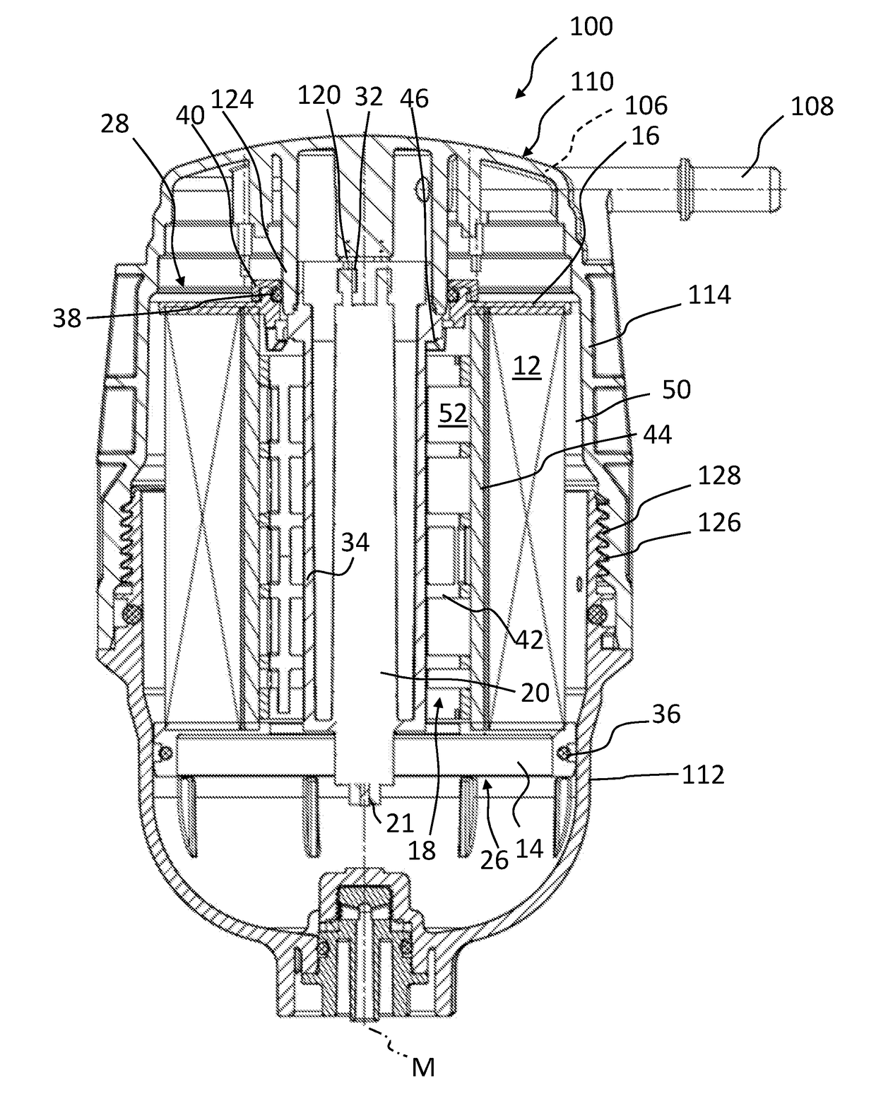
[0037]FIG. 1 shows a longitudinal section of a filter system 100 for filtering a fluid according to an embodiment of the invention with a filter housing 110 to which a central element 20 with a strainer filter 34 is fastened. The filter system 100 comprises a filter housing 110 with a housing axis M, a housing top part 114 and a housing bottom part 112 disposed along the housing axis M, an inlet socket 106 arranged at the housing top part 114 for supplying a fluid to be filtered, and an outlet socket 108 arranged at the housing top part 114 for discharging the filtered fluid. The inlet socket 106 cannot be seen in section view; it guides, at the marked location (106), the fluid to the raw fluid side 50 of the housing top part 114. Moreover, the filter system 100 comprises a filter element 10 that fluid-tightly separ...


PUM


Abstract

A filter system for filtering a fluid is provided with a filter housing that has a housing top part and a housing bottom part arranged along a housing axis of the filter housing. An inlet socket is arranged at the housing top part for supplying a fluid to be filtered. An outlet socket is arranged at the housing top part for discharging the fluid. A filter element is provided with a filter bellows arranged about a longitudinal axis of the filter element. The filter element, installed inside the filter housing, fluidically separates a raw fluid side from a clean fluid side. A central element is attached to the filter housing and extends along the housing axis. The central element is separate from the filter element and projects into an interior of the filter element. A strainer filter is arranged at the central element.

Description

TECHNICAL FIELD[0001]The invention concerns a filter system, with a central element and a strainer filter, for filtering a fluid, in particular for a fuel filter of an internal combustion engine, as well as a filter housing and a filter element for such a filter system.BACKGROUND OF THE INVENTION[0002]DE 10 2013 009 198 A1 discloses a fuel filter with a filter housing and with an element-associated electrical connecting element and with a housing-associated electrical connecting element, in which the element-associated connecting element and the housing-associated connecting element are electrically connected to each other when the filter element is installed in the filter housing. In the filter housing, a guiding ramp with a ramp surface is arranged. Upon insertion of the filter element into the filter housing in axial direction relative to the filter axis with the connecting end face leading, the element-associated connecting element and another section of the connecting end face ...

Claims


Application Information

Patent Timeline
IPC IPC(8): B01D29/21B01D29/58B01D35/18B01D17/04B01D36/00
CPCB01D29/21B01D29/58B01D35/18B01D17/045B01D36/005B01D2201/347B01D29/11B01D35/30B01D35/306B01D36/003B01D2201/295B01D2201/305B01D2201/4084
Inventor AMMERSDOERFER, MICHA
Owner MANN HUMMEL GMBH