

Display change mechanism
a technology of display mechanism and display, which is applied in the field of display mechanism, can solve the problems of thicker watches and complicated reading of indications
- Summary
- Abstract
- Description
- Claims
- Application Information
AI Technical Summary
Benefits of technology
Problems solved by technology
Method used
Image

Examples
Embodiment Construction
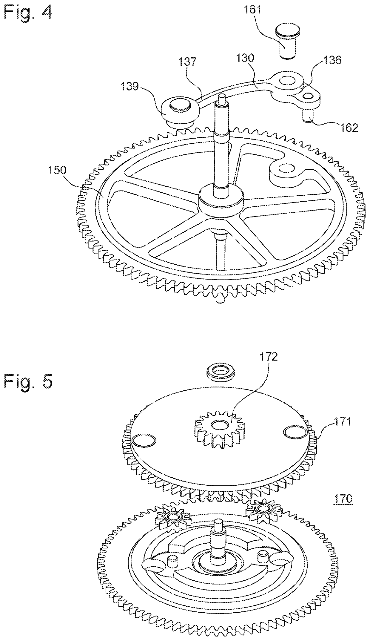
[0080]The present invention proposes to display and in particular to indicate two pieces of information via a single display mobile 150, illustrated in FIG. 4, so as to be able to arrange several indications while keeping a clean dial design.
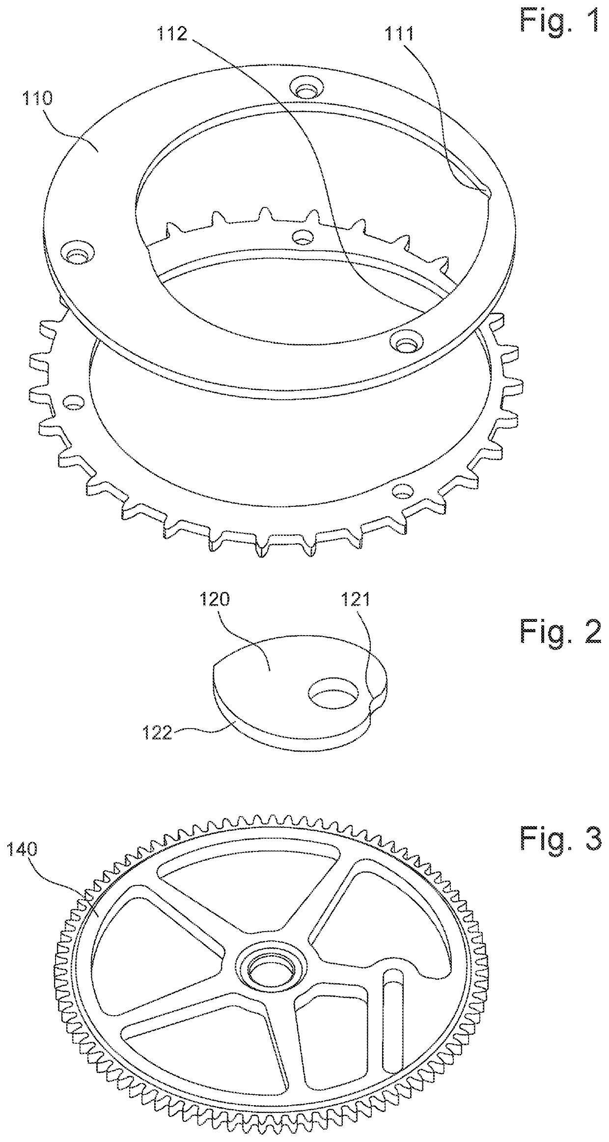
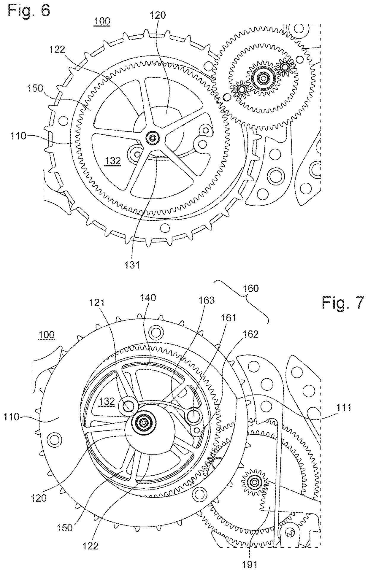
[0081]For this purpose, the invention is in the form of a display mechanism 100 comprising at least one first counter 110, shown in FIG. 1, configured to be movable and to indicate a first piece of information and at least one second counter 120, shown in FIG. 2, also configured to be movable and also to indicate a second piece of information.
[0082]Typically, as shown in FIG. 1, said at least one first counter 110 may be in the shape of a first display cam 110 or a first display core 110, just like said at least one second counter 120, which can also be a second display cam 120 or a second display core 120, see for example FIG. 2.
[0083]Said display mechanism 100 of the present invention also comprises at least one display mobile 150, typically a...
PUM
 Abstract
Description
Claims
Application Information