

Golf-putters
a golf and putter technology, applied in golf clubs, golf, sport apparatus, etc., can solve the problems of reducing the degree of error and the degree of dimple error of the face, and achieve the effect of more delicate surface structures
Inactive Publication Date: 2005-02-01
LINDSAY NORMAN MATHESON
View PDF16 Cites 82 Cited by
- Summary
- Abstract
- Description
- Claims
- Application Information
AI Technical Summary
Benefits of technology
A re-entrant ridge-profile (profile narrowing with depth) can be used with soft materials; in this case the TSF can be as large as 0.72. Also, the gaps between ridges may be filled or partially filled with a material that is softer than the ridge material; this prevents extra
Problems solved by technology
Further measurements show that modifications to the impact face can markedly alter the degree of dimple error.
However, in some cases altering the shape of the impa
Method used
View moreImage
Smart ImageViewing Examples

Examples
 PUM
 Abstract
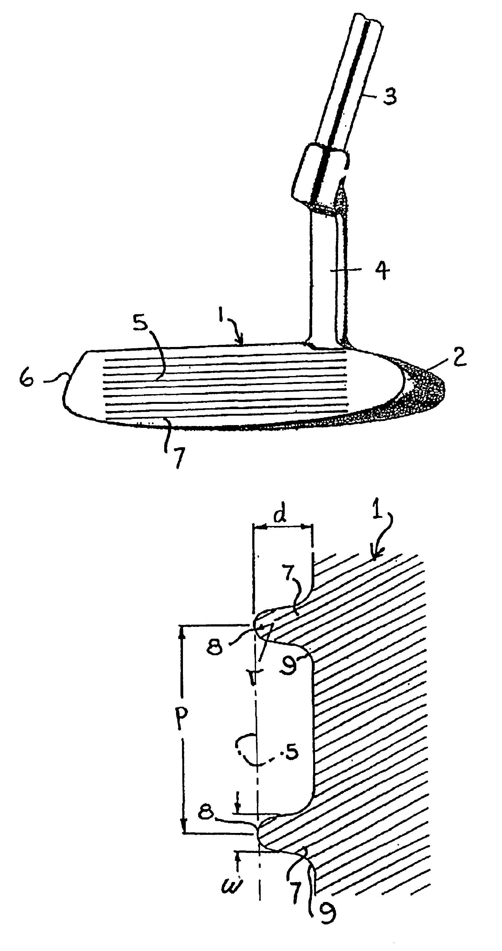
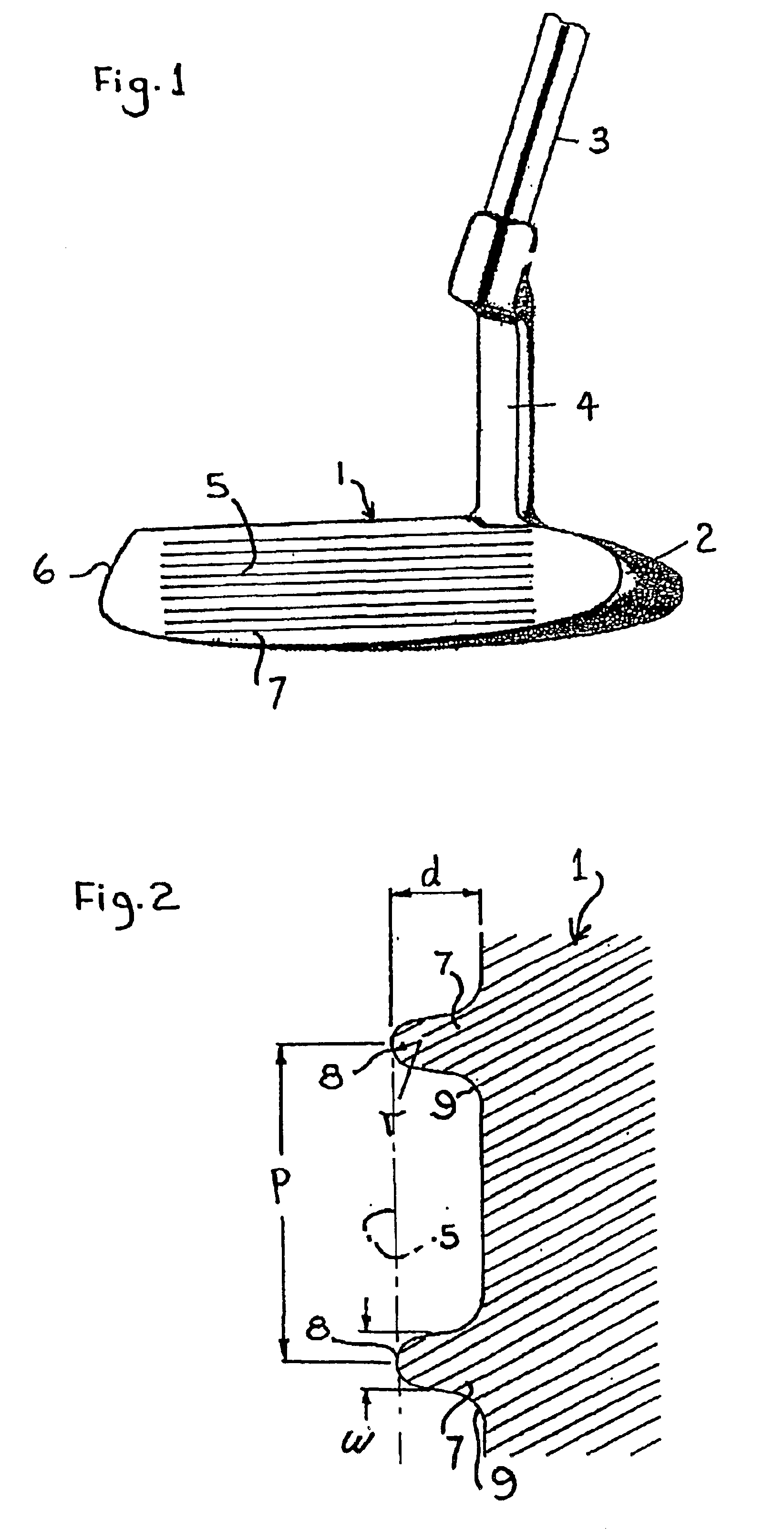
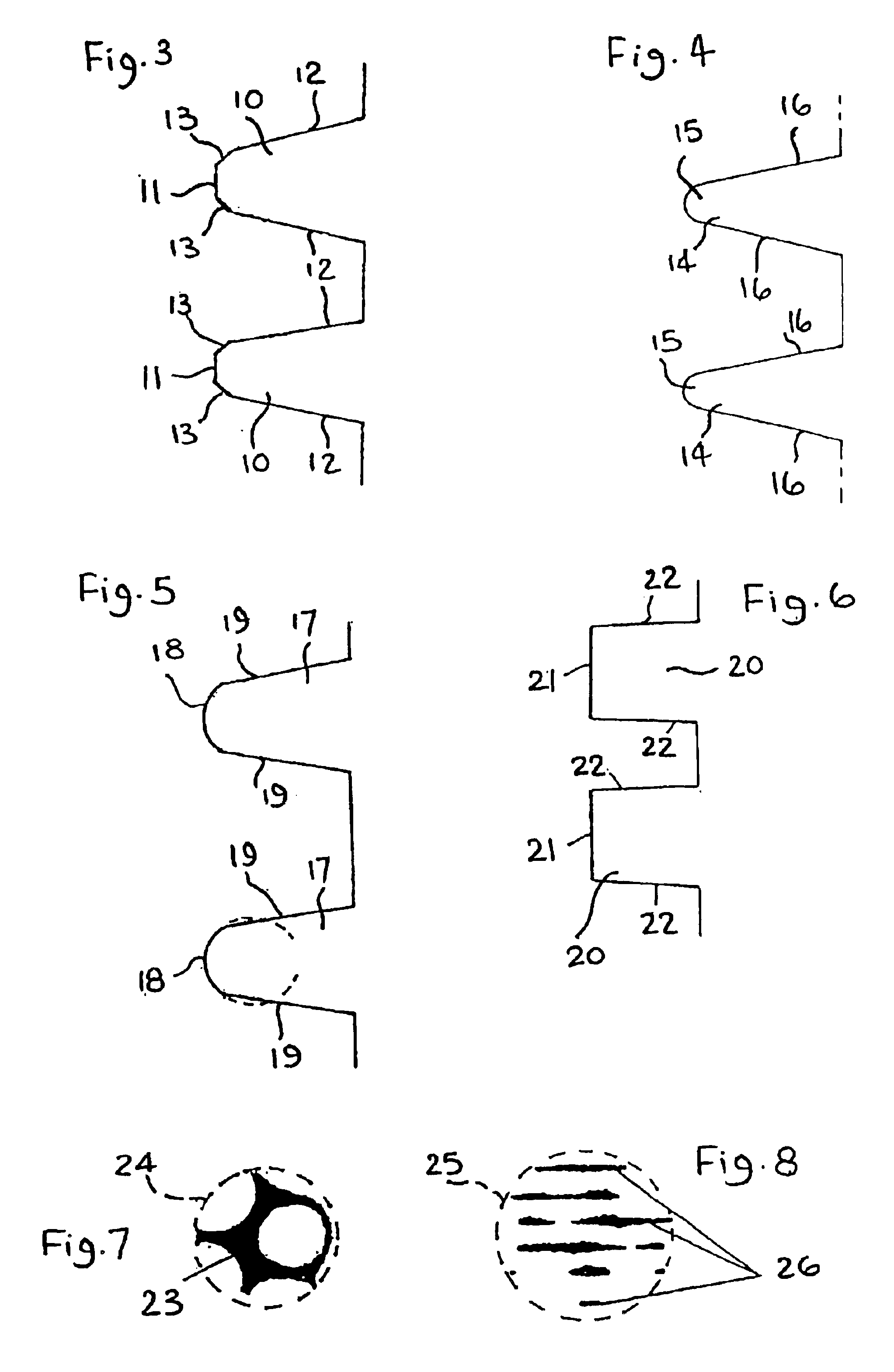
A golf-putter head (1) has a grooved impact face (5) defining lengthwise ridges (7) for impacting a dimpled golf-ball in areas of contact that are distributed around the dimples for improvement of putt accuracy by collectively centralizing the resultant striking force on the ball. The profile, width w and pitch p of the ridges (7) are selected according to hardness h and with p and w not exceeding 3.5 mm and (p−0.4) mm respectively, to reduce the standard deviation of dimple-effect error distribution by at least 15% in putting with initial ball-velocity of 2.5 m/s. Ridge-profile is symmetrically rounded (FIGS. 2,4,5,21), flat (FIG. 6,20) or segmented-flat (FIG. 3), or asymmetrical (FIG. 19), and test apparatus (FIGS. 11, 12) uses a linear actuator (33) for projecting the ball repeatedly to drop onto an impact-recording plate (36) to reveal scatter due to dimple-effect error.
Description
FIELD OF THE INVENTIONThis invention relates to golf-putters.BACKGROUND OF THE INVENTIONIt is known that even if a golf ball is putted with a ‘perfect robot’ (or any other form of precision mechanism) on a ‘perfect putting surface’, there will still be significant variation in the resulting ball-direction. The variation may be caused by spherical asymmetry in the mass and / or shape of the ball and by surface irregularities, in particular, in the dimpled-surface pattern. The dimpled pattern is an inherent part of golf-ball design and is provided to enhance aerodynamic performance.In putting, the impact footprint (that is, the area of contact between ball and putter) has a span of the order of 5 millimeters, which is comparable with dimple-diameter. Since dimples cause voids in the contact between the impact face of the putter and the golf-ball surface, the impact footprint is rarely symmetrical. Moreover, the distribution of the striking force is not uniform across the footprint, but ...
Claims
Login to View More Application Information
Patent Timeline
 IPC IPC(8): A63B53/04A63B53/02
CPCA63B53/0487A63B2053/021A63B2053/0445A63B2053/0416A63B2053/0408A63B53/021A63B53/0408A63B53/0416A63B53/0445
InventorLINDSAY, NORMAN MATHESON
OwnerLINDSAY NORMAN MATHESON