Numeral lock structure

a numeral wheel and lock core technology, applied in padlocks, coupling devices, electrical devices, etc., can solve the problems of poor burglarproof effect of lock structure, thief can easily knock out the lock hook and damage the lock core, and limited structural strength of sections of numeral wheels engaged with the lock core, etc., to achieve convenient use

Inactive Publication Date: 2005-03-01
YU CHUN TE
View PDF15 Cites 60 Cited by
  • Summary
  • Abstract
  • Description
  • Claims
  • Application Information

AI Technical Summary

Benefits of technology

It is therefore a primary object of the present invention to provide a numeral lock structure including: a lock main body in which a lock core is arranged, the lock core being controlled by multiple numeral wheels to lock or unlock; a lock hook having a base end and an extending free end, the base end being pivotally inserted in one end of the lock main body, whereby the free end of the lock hook can be freely rotated about the base end; and a displaceable button disposed on the lock main body for restricting the free end of the lock hook. Top side of the displaceable button is formed with a notch in which the free end of the lock hook is restricted in a locked state. When the lock core is locked, the displaceable button is synchronously restricted from displacing to keep locking the lock hook. When the lock core is unlocked, the displaceable button is synchronously displaceable, permitting the free end of the lock hook to be turned outward and detach out from the notch for unlocking. When the numeral wheels are turned to the correct number, the lock core is unlocked. At this time, a user can hold the lock main body and at the same time rotate the displaceable button to pen the lock hook with single hand. This is convenient to the user.

Problems solved by technology

This is inconvenient.2. The lock hook is directly connected with the lock core which is restricted by the numeral wheels.
The sections of the numeral wheels engaged with the lock core have limited structural strength.
Therefore, a thief can easily knock out the lock hook to damage the lock core.
Accordingly, such lock structure has poor burglarproof effect.

Method used


Image

  • Numeral lock structure
  • Numeral lock structure
  • Numeral lock structure

Examples


first embodiment

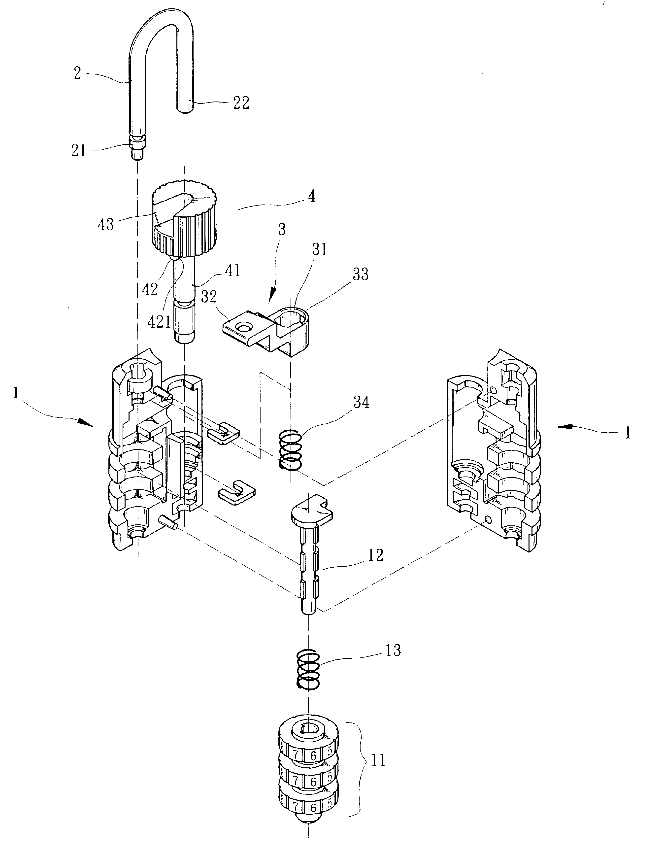
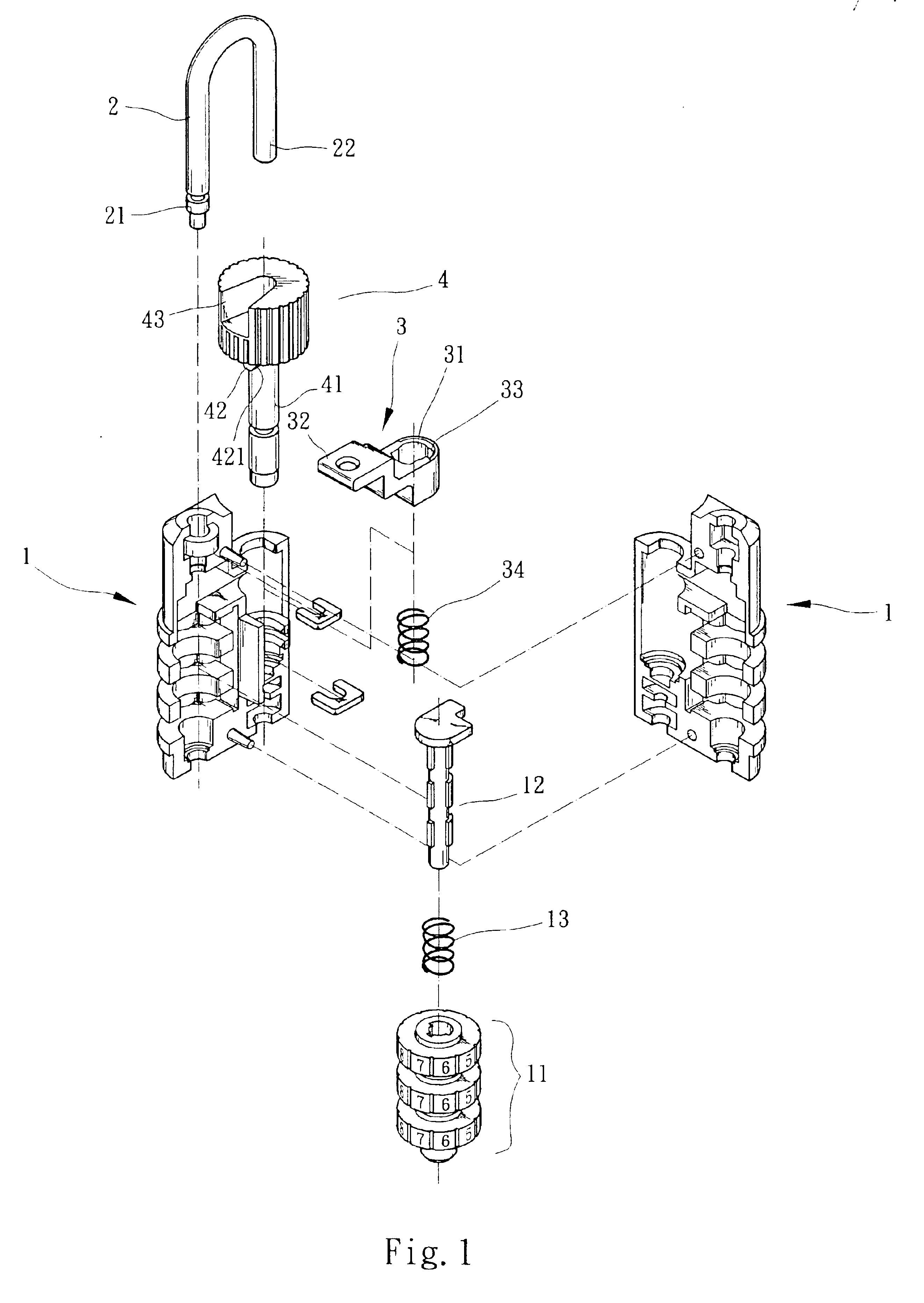
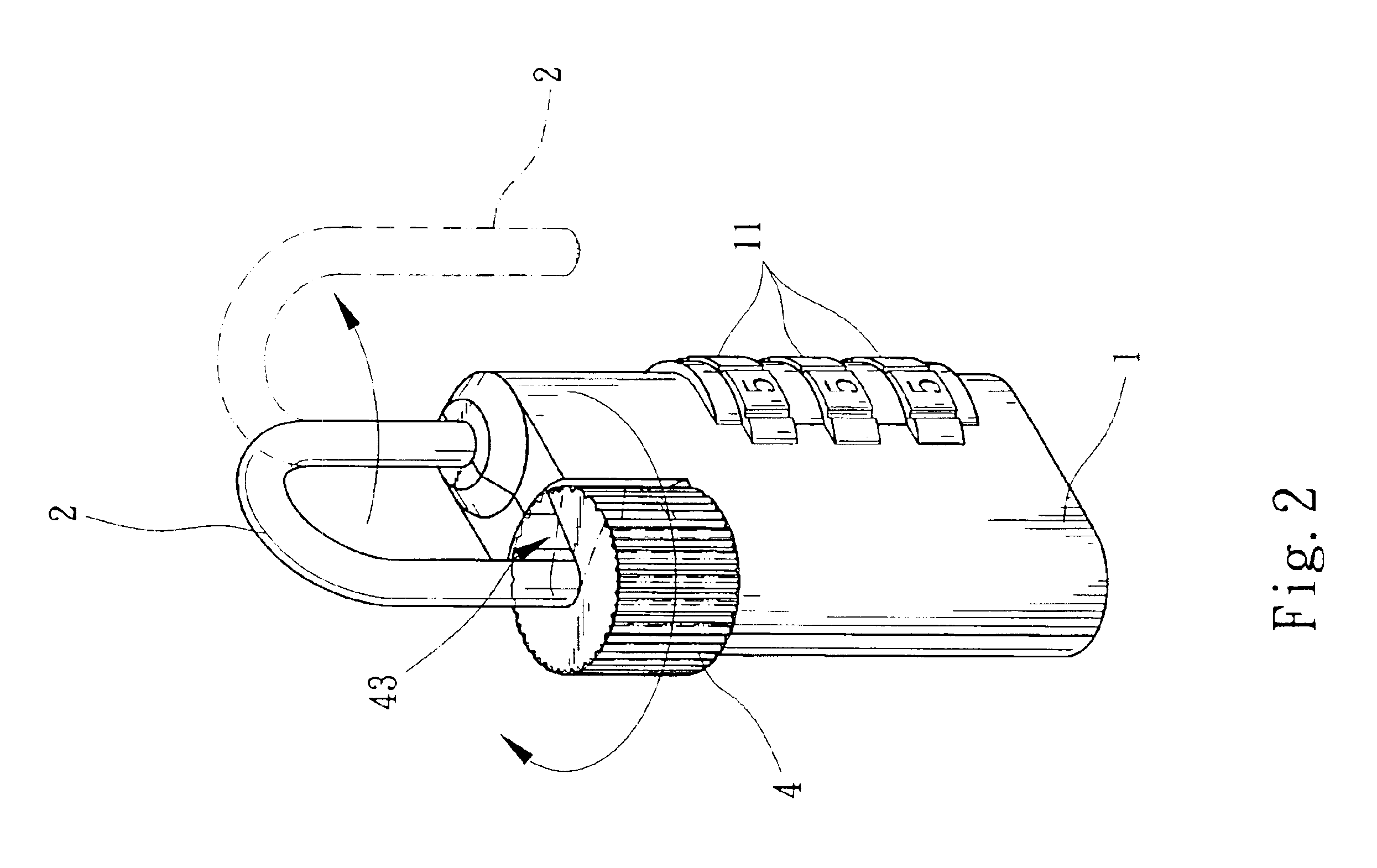
Please refer to FIG. 1 which shows the present invention. The numeral lock includes a lock main body 1, a lock hook 2, a linking member 3 and a rotary displaceable button 4. A lock core 12 is arranged in the lock main body 1. Multiple numeral wheels 11 are fitted on the lock core 12. When the numeral wheels 11 are turned to the correct number, the lock core 12 can be unlocked and moved. A resilient member 13 such as a spring is fitted on the lock core 12. The resilient member 13 is compressed between the top end of the lock core 12 and the numeral wheels 11, whereby in normal state, the lock core 12 is resiliently forced to abut against the linking member 3. The lock hook 2 is substantially U-shaped and has a base end 21 and an extending free end 22. The base end 21 is pivotally inserted in one end of the lock main body 1, whereby the lock hook 2 can be freely rotated about the base end 21. The linking member 3 is formed with a central through shaft hole 31. The circumference of top...

second embodiment

FIGS. 5 and 6 show the present invention, in which the lock core 102 is disposed in the lock main body 10 and controllable by the numeral wheels 101. The lock core 102 is drivingly connected with a displaceable button 30 extending out from upper end of the lock main body 10. A resilient member 103 resiliently forces the displaceable button 30 outward. An outer side of the top of the displaceable button 30 is formed with a lock hole 301. A lock hook 20 is disposed on upper end of the lock main body 10. A base end 201 of the lock hook 20 is pivotally inserted in the lock main body 10, whereby the lock hook 20 can be rotated about the base end 201. The other end of the lock hook 20 is a free end 202 which can be inserted into the lock hole 301 of the displaceable button 30 in natural state. When the numeral wheels 101 are positioned in locked position, the lock core 102 is engaged and prevented from moving. The top end of the lock core 102 abuts against the bottom end of the displaceab...


PUM


Abstract

A numeral lock structure including: a lock main body in which a lock core is arranged, the lock core being controlled by multiple numeral wheels to lock or unlock; a lock hook having a base end and an extending free end, the base end being pivotally inserted in one end of the lock main body, whereby the free end of the lock hook can be freely rotated about the base end; and a displaceable button disposed on the lock main body for restricting the free end of the lock hook. Top side of the displaceable button is formed with a notch in which the free end of the lock hook is restricted in a locked state. When the lock core is locked, the displaceable button is synchronously restricted from displacing to keep locking the lock book. When the lock core is unlocked, the displaceable button is synchronously displaceable, permitting the free end of the lock hook to be turned outward and detach out from the notch for unlocking.

Description

BACKGROUND OF THE INVENTIONThe present invention is related to an improved numeral lock structure, and more particularly to a numeral lock having simple structure and can be conveniently operated to achieve better burglarproof effect.In a conventional numeral lock, a lock core is disposed in a lock body. The lock core is connected with an outward extending U-shaped lock hook. A free end of the lock hook can be inserted and locked in the lock hole formed on the lock body. Multiple numeral wheels are fitted around the lock core. The numerals on the surfaces of the numeral wheels are exposed to outer side of the lock body. In use, the numeral wheels are turned to preset unlocking number to unlock the lock core. Then the lock hook is tracked outward to extract the free end of the lock hook from the lock hole. Such structure has some shortcomings as follows:1. After the lock core is released from the locking of the numeral wheels, a user needs to hold the lock body with one hand and pull...

Claims


Application Information

Patent Timeline
Patent Type & Authority Patents(United States)
IPC IPC(8): E05B37/06E05B37/00H01R12/00H01R12/22E05B37/02E05B67/10H01R12/71
CPCE05B67/10E05B37/025Y10T70/424Y10T70/43Y10T70/7305
Inventor YU, CHUN-TE
Owner YU CHUN TE
Why Eureka
Try Eureka