Connector assembly

Inactive Publication Date: 2005-09-20
CHENG UEI PRECISION IND CO LTD
View PDF9 Cites 45 Cited by
  • Summary
  • Abstract
  • Description
  • Claims
  • Application Information

AI Technical Summary

Benefits of technology

[0011]As mentioned above, while the plug and the receptacle mate each other, the first engaging portions of the first plug contacts connect electrically correspondingly with the first conductive portions of the first receptacle contacts, and the second engaging portions of the second plug contacts connect electrically correspondingly with the second conductive portions of the second

Problems solved by technology

However, because of a limit of the standard USB structure and the restricted terminal number, the conventional USB conne

Method used


Image

  • Connector assembly
  • Connector assembly
  • Connector assembly

Examples


Embodiment Construction

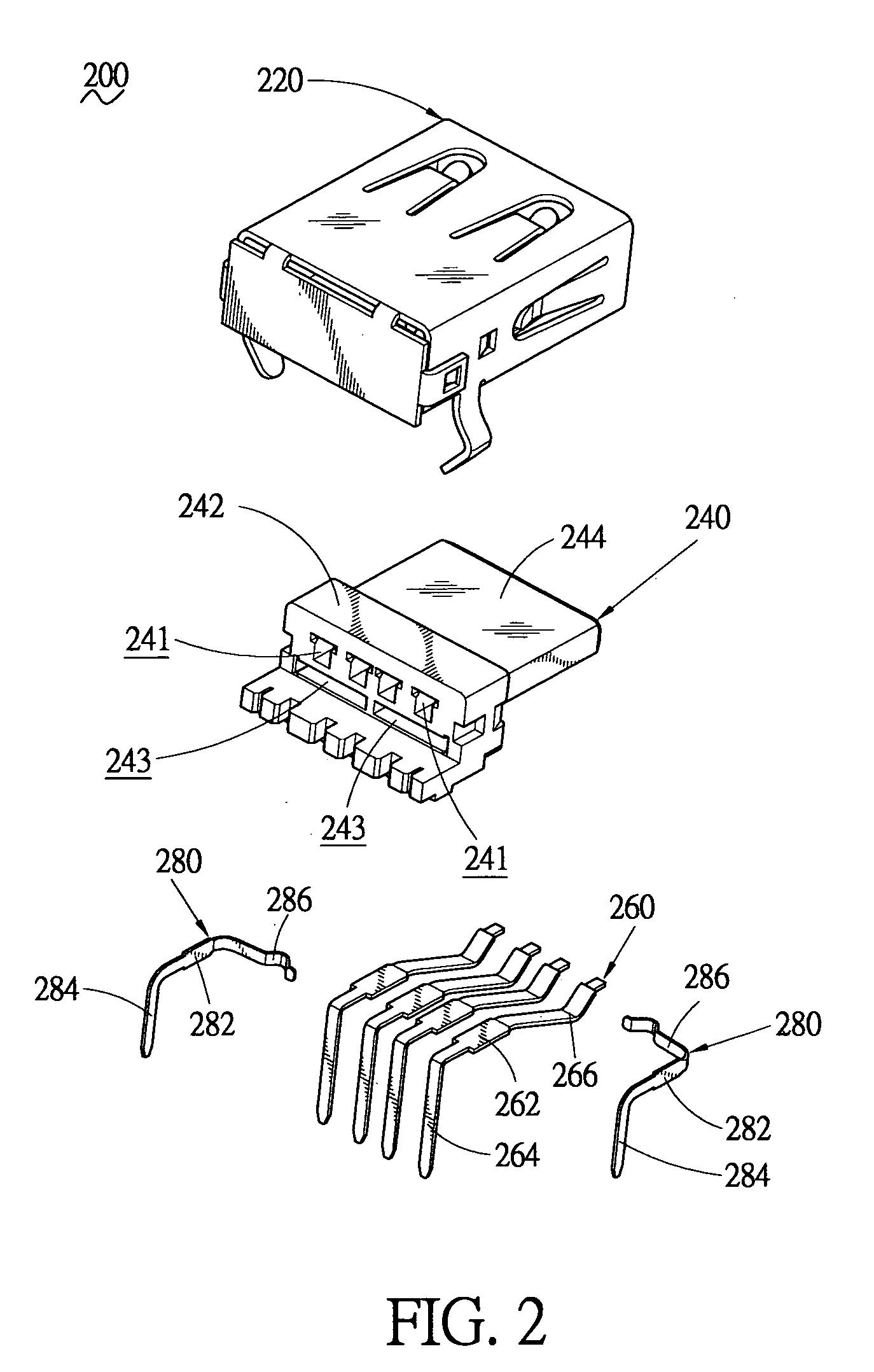
[0019]A connector assembly in accordance with the present invention is generally denoted by reference numeral 1 as shown in FIG. 5. With first reference to FIGS. 1 and 2, the connector assembly 1 comprises a plug 100 and a receptacle 200 adapted to mate each other.

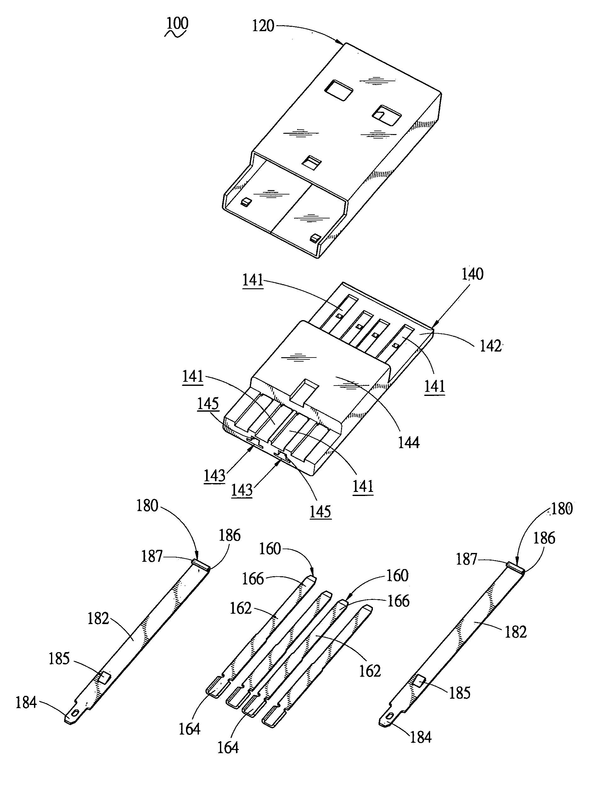
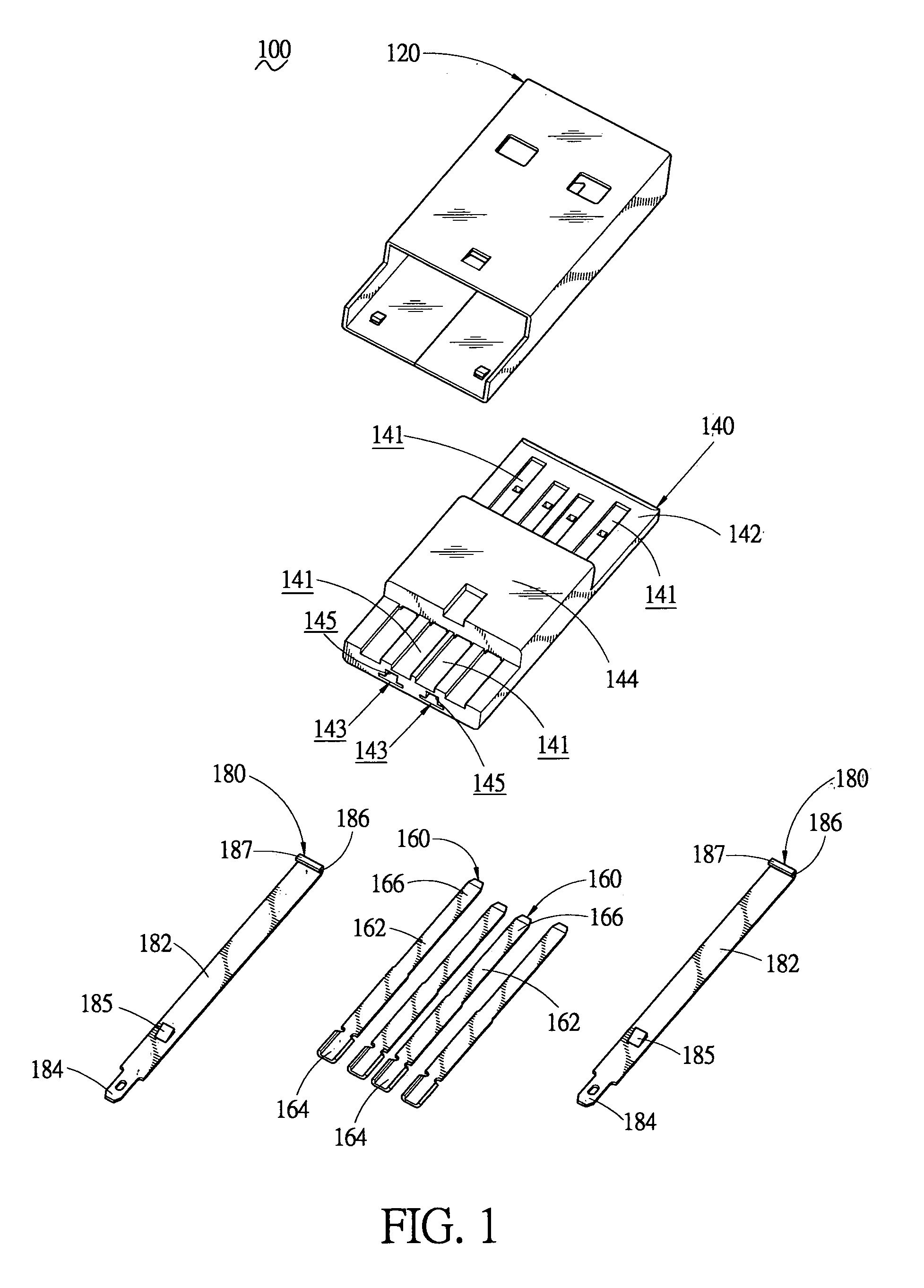
[0020]As shown in FIG. 1, the plug 100 includes a plug housing 140 enclosed within a plug shell 120. The plug housing 140 receives a plurality of first plug contacts 160 and second plug contacts 180 therein.

[0021]The plug housing 140 has a base body 142 with a protruding body 144 extending upwardly from the substantial middle part thereof. The base body 142 is lengthwise defined with a plurality of first plug contact grooves 141 on the top surface thereof for receiving the first plug contacts 160 therein. Each first plug contact groove 141 passes through a lower surface of the protruding body 144, with one end thereof extending rearwards through the base body 142, and the other end thereof extending forwardly to reach a fr...


PUM


Abstract

The present invention provides a connector assembly, which includes a USB (Universal Serial Bus) plug and a USB receptacle. The plug and receptacle both have a plurality of first contacts and second contacts. The first contacts include a pair of power contacts and a pair of signal contacts, and the second contacts are composed of a pair of new signal contacts. When the plug mates with the receptacle, the first and the second contacts of the plug and receptacle connect electrically with each other correspondingly whereby the connector assembly of the present invention has a more powerful signal transmission function.

Description

BACKGROUND OF THE INVENTION[0001]1. Field of the Invention[0002]The present invention relates generally to a connector assembly, and more especially to a USB (Universal Serial Bus) connector assembly.[0003]2. The Related Art[0004]As we know, since the USB connector has many features, such as “Plug and Play”, “hot-swapping”, and a high signal transmission speed etc., it has an extensive application field, especially in the computer and peripherals field.[0005]In general, a USB connector assembly includes a plug and a receptacle adapted to mate each other. Both the conventional plug and receptacle receive a pair of power terminals and a pair of signal terminals therein. As using, the power and signal terminals of the plug and receptacle connect electrically correspondingly, thereby the power and the signal could be transferred therebetween.[0006]At present, following with users constantly ask high requirement to enhance the computer and peripherals products function, the trend of vari...

Claims


Application Information

Patent Timeline
IPC IPC(8): H01R33/00H01R13/26H01R13/658H01R24/00
CPCH01R13/26H01R12/716H01R13/65802H01R13/6582
Inventor LI, YUDU, GAOHUAXU, LI JUN
Owner CHENG UEI PRECISION IND CO LTD
Why Eureka
Try Eureka