Arrangement for connecting additional antenna to radio device

a radio device and antenna technology, applied in the direction of antenna details, antenna adaptation in movable bodies, antennas, etc., can solve the problems of degrading the matching of the antenna, affecting the operation band of the antenna, and requiring relatively high cost and reliability, so as to achieve relatively small cost and relatively efficient coupling

Inactive Publication Date: 2006-07-25
PULSE FINLAND
View PDF15 Cites 70 Cited by
  • Summary
  • Abstract
  • Description
  • Claims
  • Application Information

AI Technical Summary

Benefits of technology

[0009]An advantage of the invention is that the coupling is relatively efficient: transmitting energy for the additional antenna is gathered both from the field of the inner planar antenna and from the field corresponding to the radio frequency currents flowing in the ground plane of the radio device. Another advantage of the invention is that the effect of the introduction of an additional antenna on the location of the operating band is small in spite of the efficiency of the coupling. A further advantage of the invention is that the arrangement according to it is reliable and involves relatively small costs.
is that the coupling is relatively efficient: transmitting energy for the additional antenna is gathered both from the field of the inner planar antenna and from the field corresponding to the radio frequency currents flowing in the ground plane of the radio device. Another advantage of the invention is that the effect of the introduction of an additional antenna on the location of the operating band is small in spite of the efficiency of the coupling. A further advantage of the invention is that the arrangement according to it is reliable and involves relatively small costs.

Problems solved by technology

Such a connector arrangement based on galvanic contact is, however, relatively expensive and unreliable in the long term.
A disadvantage of this solution is that the attachment of the coupling part may significantly shift the operating band of the antenna and degrade the matching of the antenna at least in part of the operating band.
A drawback of the connection arrangement of FIG. 2 is that it cannot be applied to a radio device having an internal antenna.

Method used


Image

  • Arrangement for connecting additional antenna to radio device
  • Arrangement for connecting additional antenna to radio device
  • Arrangement for connecting additional antenna to radio device

Examples


Embodiment Construction

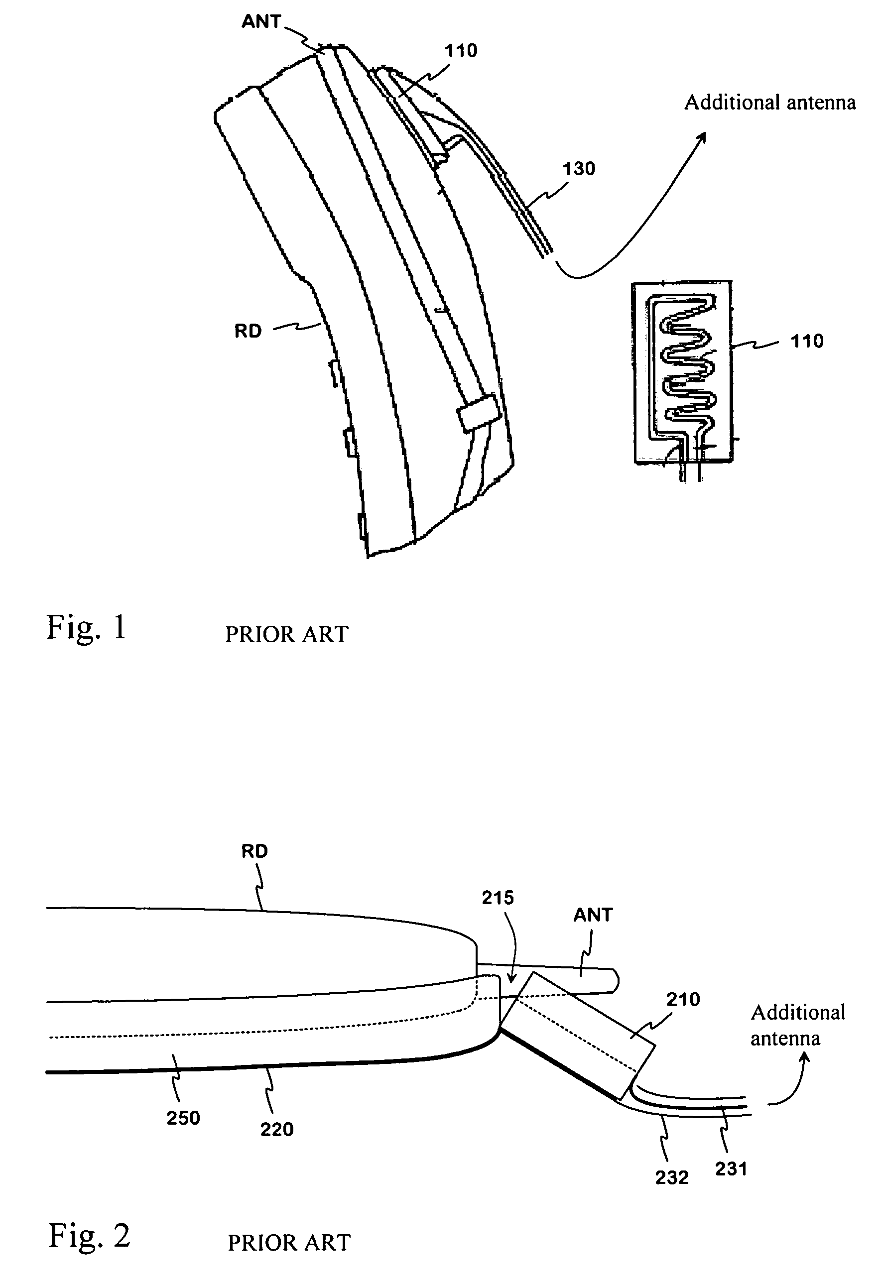
[0018]FIGS. 1 and 2 were already discussed in conjunction with the description of the prior art.

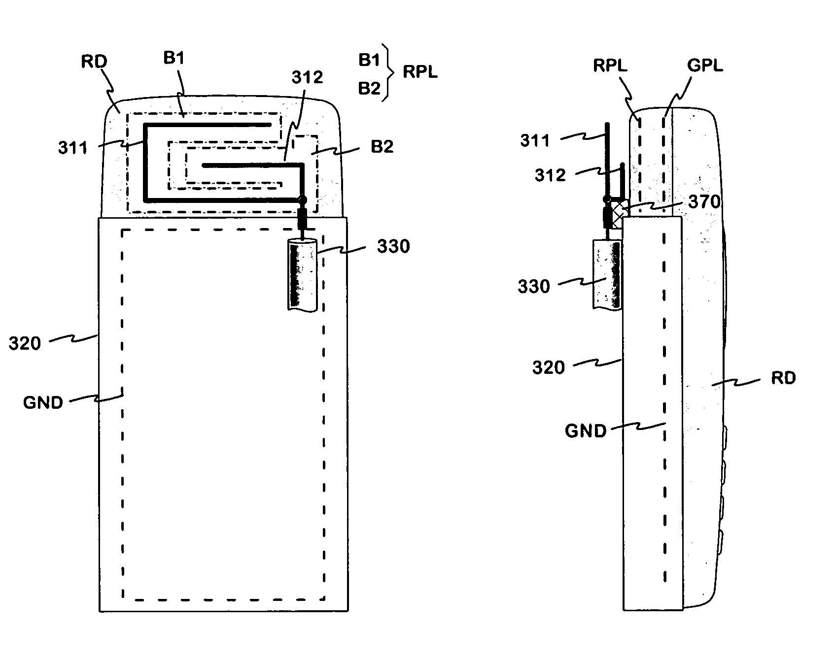
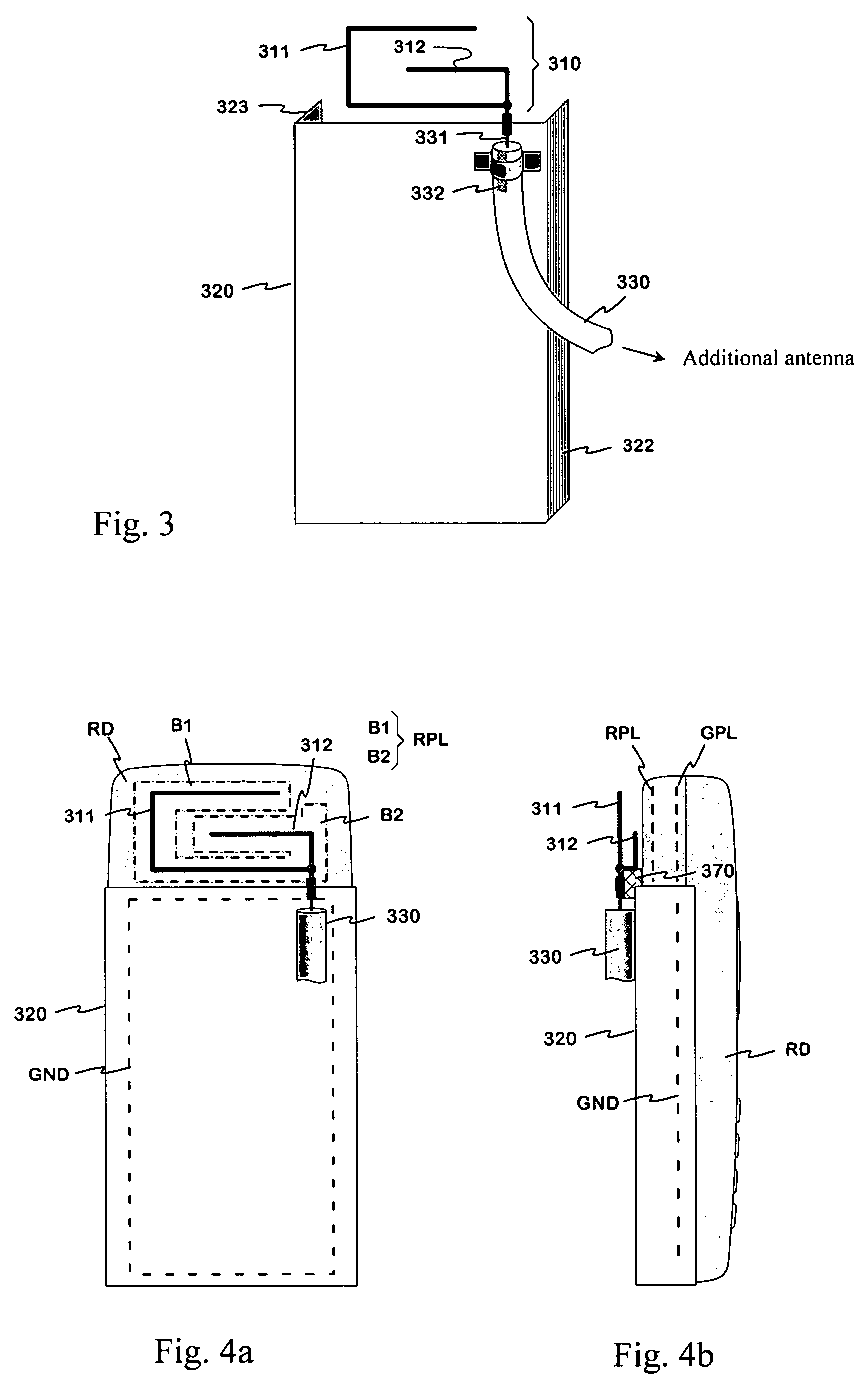
[0019]FIG. 3 shows an example of a device according to the invention for connecting an additional antenna. The device comprises a first coupling part 310, second coupling part 320, and an intermediate cable 330. The first coupling part is intended to be placed over the planar antenna of the radio device and it comprises two coupling conductors 311 and 312 which in this example are rigid conductive wires. These are interconnected such that they have, viewed from below in figure, a short common part followed by two branches. The second coupling part 320 is intended to be placed over the ground plane of the radio device and comprises a conductive plate the side fringes of which are bent at a right angle so as to form folds 322, 323. Viewed along the normal of the conductive plate 320, the coupling parts are adjacent so that the first coupling part is located close to the upper edge of the co...


PUM


Abstract

An arrangement for connecting an additional antenna to a portable radio device (RD) having an internal planar antenna. Energy for the additional antenna is taken from the near field of the planar antenna, the coupling elements being provided by conductors (311, 312) located outside the covering of the radio device and following the conductive branches (B1, B2) of the radiating plane (RPL) of the planar antenna. The arrangement further comprises a conductive plate (320) located in front of and parallel to the ground plane (GND) in the radio device to take energy from the field of the ground plane. The inner conductor of the cable (330) for the additional antenna is galvanically connected to the conductors placed over the planar antenna, and the sheath is galvanically connected to the conductive plate (320) near the connection point of the inner conductor.

Description

CROSS REFERENCE TO PRIOR APPLICATION[0001]This application is a continuation of International Patent Application Serial No. PCT / FI2003 / 000892, filed Nov. 20, 2003, which claims priority of Finnish Application No. 20022117, filed Dec. 2, 2002, both of which are incorporated by reference herein. PCT / FI2003 / 000892 published in English on Jun. 17, 2004 as WO 2004 / 051799 A1.[0002]The invention relates to an arrangement for connecting an additional antenna to a portable radio device, especially a mobile station, to enhance radiocommunications.BACKGROUND OF THE INVENTION[0003]In practice, an additional antenna for a mobile phone or some other mobile communication device is most often used in a vehicle as the base station's field strength is low within the body of the vehicle. The additional antenna is in that case naturally situated outside the body of the vehicle, attached thereto. For using an external antenna the vehicle may include a fixed holder so that a phone placed in the holder wi...

Claims


Application Information

Patent Timeline
Patent Type & Authority Patents(United States)
IPC IPC(8): H01Q1/24H01Q1/32
CPCH01Q1/3208H01Q1/243
Inventor KINNUNEN, PEKKAMIKKOLA, JYRKI
Owner PULSE FINLAND
Why Eureka
Try Eureka